Advantech IPPC-7158 Series Скачать руководство пользователя страница 6

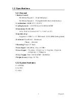
IPPC-7158 User Manual

vi

Safety Instructions                                                                                          

1.  Read these safety instructions carefully.
2. Keep this User's Manual for later reference.
3. Disconnect this equipment from any AC outlet before cleaning. Use a damp 

cloth. Do not use liquid or spray detergents for cleaning.

4.  For plug-in equipment, the power outlet socket must be located near the 

equipment and must be easily accessible.

5. Keep this equipment away from humidity.
6.  Put this equipment on a reliable surface during installation. Dropping it or let-

ting it fall may cause damage.

7.  The openings on the enclosure are for air convection. Protect the equipment 

from overheating. DO NOT COVER THE OPENINGS.

8. Make sure the voltage of the power source is correct before connecting the 

equipment to the power outlet.

9. Position the power cord so that people cannot step on it. Do not place anything 

over the power cord.

10. All cautions and warnings on the equipment should be noted.
11. If the equipment is not used for a long time, disconnect it from the power 

source to avoid damage by transient overvoltage.

12. Never pour any liquid into an opening. This may cause fire or electrical shock.
13. Never open the equipment. For safety reasons, the equipment should be 

opened only by qualified service personnel.

14. If one of the following situations arises, get the equipment checked by service 

personnel:
a. The power cord or plug is damaged.
b. Liquid has penetrated into the equipment.
c. The equipment has been exposed to moisture.
d. The equipment does not work well, or you cannot get it to work according 

to the user's manual.

e. The equipment has been dropped and damaged.
f. The equipment has obvious signs of breakage.

15. DO NOT LEAVE THIS EQUIPMENT IN AN ENVIRONMENT WHERE 

THE STORAGE TEMPERATURE MAY GO BELOW -20° C (-4° F) OR 
ABOVE 60° C (140° F). THIS COULD DAMAGE THE EQUIPMENT. THE 
EQUIPMENT SHOULD BE IN A CONTROLLED ENVIRONMENT.

16. CAUTION: DANGER OF EXPLOSION IF BATTERY IS INCORRECTLY 

REPLACED. REPLACE ONLY WITH THE SAME OR EQUIVALENT 
TYPE RECOMMENDED BY THE MANUFACTURER, DISCARD USED 
BATTERIES ACCORDING TO THE MANUFACTURER'S INSTRUC-
TIONS.

The sound pressure level at the operator's position according to IEC 704-1:1982 is 
no more than 70 dB (A).
DISCLAIMER: This set of instructions is given according to IEC 704-1. Advan-
tech disclaims all responsibility for the accuracy of any statements contained 
herein.

Содержание IPPC-7158 Series

Страница 1: ...IPPC 7158 Series 15 XGA TFT LCD Industrial Panel PC with 14 x ISA PCI PICMG Slots Passive Backplane and Membrane Keypad User Manual...

Страница 2: ...and reliable However Advantech assumes no responsibility for use of this manual nor for any infringements upon the rights of third parties which may result from such use All brand and product names me...

Страница 3: ...ses and can radiate radio frequency energy and if not installed and used in accordance with the instruction manual may cause harmful interference to radio communications Opera tion of this equipment i...

Страница 4: ...Power Cable x 2 PATA 40 PIN DMA66 Flat Cable FDD cable D Sub Flat Cable with bracket FAN power cable Simplified Chinese Manual China RoHs for IPPC 7000 series Jumper Bag mini jumper 20 IPPC 7158 Indu...

Страница 5: ...resentative or Advantech s cus tomer service center for technical support if you need additional assistance Please have the following information ready before you call Product name and serial number D...

Страница 6: ...y liquid into an opening This may cause fire or electrical shock 13 Never open the equipment For safety reasons the equipment should be opened only by qualified service personnel 14 If one of the foll...

Страница 7: ...2 1 1 USB Ports 10 Figure 2 3 Opening the Front USB Port Cover 10 2 1 2 Adjusting the LCD Brightness 10 2 2 Installing Optional Disk Drives 12 2 3 Rack Mounting 12 Chapter 3 Touchscreen 14 3 1 Introdu...

Страница 8: ...IPPC 7158 User Manual viii...

Страница 9: ...CHAPTER 1 General Information This chapter gives background information on the IPPC 7158 series Sections include Introduction Specifications Dimensions...

Страница 10: ...replace or service it simply and quickly This helps saves downtime costs associated with system crashes Secondly the side open LCD front panel also make it more convenient when you want to main tain t...

Страница 11: ...BF Dimensions W x H x D 482 x 354 8 x 162 mm 18 97 x 13 96 x 6 37 Disk Drive Bay Supports 1 x FDD 1 x 3 5 HDD and 1 X CD ROM both optional Enclosure Front Panel Aluminum Chassis Anti rust Mounting Pan...

Страница 12: ...ng Angle H V 140 120 1 2 4 Touchscreen Optional Interface USB Lifespan 10 million with silicone rubber of R8 finger writing rate is 250g at 2X s Light Transmission 80 AMT OS Support Windows 95 98 ME 2...

Страница 13: ...F10 F1 M1 Enter Right Left Space Shift Alt Ctrl Space Back Tab PgDn PgUp Delete Esc _ 0 _ _ _ 6 3 5 2 1 4 9 8 7 7 8 9 _ _ _ Esc Delete PgUp PgDn Tab Back Space Ctrl Alt Shift Space Left Right Enter M2...

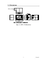
Страница 14: ...IPPC 7158 User Manual 6...

Страница 15: ...CHAPTER 2 System Setup This chapter details system setup for the IPPC 7158 Series Sections include A Quick Tour of IPPC 7158 Installing a CPU CPU Cooler Installing Optional Disk Drives Rack Mounting...

Страница 16: ...PU card to install the system each jumper setting and CPU chosen based on it s own specification 2 Switch off and unplug the computer every time you access its interior 3 The motherboard inside the sy...

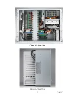
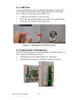
Страница 17: ...9 Chapter2 Figure 2 1 Open View Figure 2 2 Side View...

Страница 18: ...ternal device to the system 2 The USB ports support hot plug in connection You should install the device driver before you use the device Figure 2 3 Opening the Front USB Port Cover 2 1 2 Adjusting th...

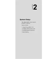
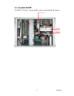
Страница 19: ...11 Chapter2 2 1 3 System On Off The IPPC 7158 has 1 system on off switch located inside the chassis...

Страница 20: ...the front LCD panel Below is the procedure of installing HDD and CD ROM 1 Unscrew the 3 screws and 4 screws on the side of the case to remove the HDD Drive Bay 2 Unscrew the 4 Screws on the bottom of...

Страница 21: ...creen This chapter contains information on the touchscreen its installation and configuration Sections include Introduction Installing Windows 2000 XP Drivers Configuring PenMount Drivers Uninstalling...

Страница 22: ...Class B standards 3 2 Touchscreen Driver Installation Configuration The touchscreen of IPPC 7158 is controlled by USB interface and has drivers for Linux Windows 2000 Windows XP Windows Vista and Win...

Страница 23: ...Appendix A LCD Specifications and Selection Settings...

Страница 24: ...250 cd sq meter Viewing area 304 128 H x 228 096 mm Power consumption 10 7 W Typ 6 0mA Gray Bar Pattern Operating temperature 0 50 C Storage temperature 20 60 C Backlight MTBF 60 000 hours Note The co...

Страница 25: ...Appendix B Pin Assignments...

Страница 26: ...33 MHz PCI slot KB1 KB In or KB Out connector 90 P KB2 KB3 KB In or KB Out connector 180 P KB4 KB Out external connector AT1 Main AT Power connector supply 5V 12V ATX1 Main ATX Power connector supply...

Страница 27: ...finitions Pin Definition 1 3 3V 2 3 3V 3 COM 4 5V 5 COM 6 5V 7 COM 8 Power OK 9 5VSB Standby 10 12V 11 3 3V 12 12V 13 COM 14 PS ON 15 COM 16 COM 17 COM 18 5V 19 5V 20 5V KB1 KB2 KB3 KB4 Pin Name 1 KBC...

Страница 28: ...IPPC 7158 User Manual 20 AT1 Pin Name 1 NC 2 5V 3 12V 4 12V 5 GND 6 GND 7 GND 8 GND 9 5V 10 5V 11 5V 12 5V BIG1 Pin Name 1 12V 2 GND 3 GND 4 5V CN1 Pin Name 1 PS ON 2 GND 3 5VSB...

Страница 29: ...21 AppendixB CN2 Pin Name 1 5VSB 2 GND 3 GND 4 5V 5 5V 6 3 3V 7 12V 8 12V CN3 Pin Name 1 12V 2 GND 3 5V CN4 Pin Name 1 GND 2 12V 3 NC...

Страница 30: ...INTD PPCI1 P_ AD31 INTB INTC INTD INTA PPCI2 P_ AD30 INTC INTD INTA INTB PPCI3 P_ AD29 INTD INTA INTB INTC Primary PCI Group PCI SLOT ID SEL PCI Interrupt Pin Route INTA INTB INTC INTD SPCI1 P_ AD20 I...

Страница 31: ...Appendix C Keyboard Translator...

Страница 32: ...mbrane keypad to the standard AT keyboard There are six connectors on the board On top of the board there are two connectors linking two flat cables to the membrane keypad as shown in Fig 4 3 On the s...

Страница 33: ...n of front panel macro keys M1 M10 then programmed the functions into KBT 2002 Please be notified that the SF1 SF10 in the utility program which is exactly mapping to the macro keys M1 M10 on the fron...

Страница 34: ...t panel door of IPPC 7158 3 The Keyboard Translator will be located on the back of the front panel behind the mylar protect Seebelow 4 Unscrew the screws on the mylar and remove it 5 Remove the keypad...

Отзывы: