Advantech IPC-603MB Скачать руководство пользователя страница 22

IPC-603MB User Manual

12

Содержание IPC-603MB

Страница 1: ...IPC 603MB Ultra Compact 2U high Rack mount IPC Chassis User Manual...

Страница 2: ...responsibility for its use nor for any infringements of the rights of third parties which may result from its use Acknowledgements Intel and Pentium are trademarks of Intel Corporation Microsoft Windo...

Страница 3: ...lacement materials service time and freight Please consult your dealer for more details If you think you have a defective product follow these steps 1 Collect all the information about the problem enc...

Страница 4: ...harge and EMI leakage we strongly recom mend the use of CE compliant industrial enclosure products FCC Class A This equipment has been tested and found to comply with the limits for a Class A digital...

Страница 5: ...manual we would welcome comments and constructive criticism Please send all such comments in writing to support advantech com Packing List Before setting up the system check that the items listed bel...

Страница 6: ...sonnel 14 If one of the following situations arises get the equipment checked by service personnel a The power cord or plug is damaged b Liquid has penetrated into the equipment c The equipment has be...

Страница 7: ...berhitzung sch tzt Sorgen Sie daf r daB diese ffnungen nicht abgedeckt werden 8 Beachten Sie beim AnschluB an das Stromnetz die AnschluBw erte 9 Verlegen Sie die NetzanschluBleitung so daB niemand dar...

Страница 8: ...ie die Batterie nur gleicher oder entsprechender Type wie vom Hersteller empfohlen Entsorgen Sie Batterien nach Anweisung des Herstell ers Der arbeitsplatzbezogene Schalldruckpegel nach DIN 45 635 Tei...

Страница 9: ...moving the Cover 7 2 2 Installing a Motherboard 7 2 3 Installing Disk Drives 9 2 4 Installing Add in Cards 11 2 5 Installing Rackmount Brackets Handles 11 Chapter 3 Operation 14 3 1 The Front Section...

Страница 10: ...IPC 603MB User Manual x...

Страница 11: ...2 CHAPTER 1 General Information...

Страница 12: ...el Disk drive capacity one slim type CD ROM and one internal HDD Indicators on front panel LEDs for Power and HDD Switches on front panel Power and Reset Cooling fans dual 47 CFM Air filters three 85...

Страница 13: ...oustic Noise 52dB sound pressure at 5 28 C 41 82 F Altitude Operating 0 to 3 048 m 0 10 000ft Safety CE compliant UL cUL approved 1 4 Power Supply 1U high 300 W ATX Power Supply with PFC Part Number 1...

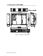
Страница 14: ...IPC 603MB User Manual 4 1 5 Dimensions of IPC 603MB Figure 1 1 Dimension of IPC 603MB...

Страница 15: ...2 CHAPTER 2 System Setup...

Страница 16: ...03MB chassis Refer to Appendix A Exploded Diagram for the names of each part used in this manual Figure 2 1 System setup Note Figure 2 1 is the summary illustration for install ing the whole IPC 603MB...

Страница 17: ...s To install a motherboard refertoFigure2 1andproceedasfollows 1 Remove the three screws from the L form riser card holder in the IPC 603MB chassis It is NOT necessary to remove the riser card from th...

Страница 18: ...or from the power supply 5 Connect the POWER SW RESET SW Power LED and HDD LED cables to the motherboard Note If you choose Advantech s AIMB 740 741 742 or 762 ATX motherboard please find a spacer bra...

Страница 19: ...e L form riser card holder together with the riser card and fasten it with screws 2 3 Installing Disk Drives The IPC 603MB accepts one slim type CD ROM RW and one internal SATA ATA HDD To install the...

Страница 20: ...type CD ROM from the bracket kit 4 Refer to Figure 2 4 and mount a slim type CD ROM RW and a 3 5 HDD with screws 5 Refer to Figure 2 5 to return the drive bay bracket kit into the IPC 603MB chassis a...

Страница 21: ...plate of the chas sis 2 Horizontally and evenly push the card leftwards until the gold fin gers are completely inserted into a PCI slot of the riser card Make sure that the card bracket has been inse...

Страница 22: ...IPC 603MB User Manual 12...

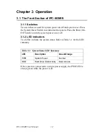
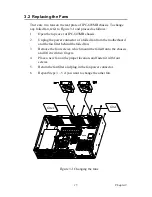
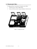
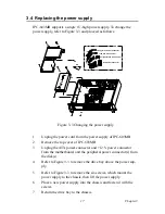
Страница 23: ...2 CHAPTER 3 Operation...

Страница 24: ...the system Press the Power On Off Switch to turn the system power on or off 3 1 2 LED indicators Two LEDs indicate the system status Refer to Table 3 1 for the LED summary If the system is connected t...

Страница 25: ...r connector of a failed fan from the motherboard and the fan filter behind the failed fan 3 Remove the four screws which mount the failed fan to the chassis and lift it with two fingers 4 Place a new...

Страница 26: ...he filters To change the filters refer to Figure 3 2 and proceed as follows 1 Open the top cover of IPC 603MB chassis 2 Remove the filter s with two fingers and replace it with a new one Figure 3 2 Ch...

Страница 27: ...power connector and 12 V power connector from the motherboard and the peripheral power connector s from the disk s 4 Refer to Figure 3 3 to remove the drive bay above the power sup ply 5 Refer to Figu...

Страница 28: ...User Manual 18 8 Plug the ATX power connector and 12V power connector into the motherboard and the peripheral power connector s into the proper disk s 9 Replace the cover of IPC 603MB and plug in the...

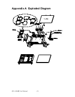
Страница 29: ...2 APPENDIX A Exploded Diagram...

Страница 30: ...IPC 603MB User Manual 20 Appendix A Exploded Diagram...

Отзывы: