Advanced Poly-Packaging US-4000 Скачать руководство пользователя страница 33

Содержание US-4000

Страница 1: ...ron OH 44306 330 785 4000 Fax 330 785 4010 www advancedpoly com sales advancedpoly com U K Advanced Poly Packaging UK Ltd Over Causeway Over Glouchester GL2 8DB 44 1452 332400 Fax 44 1452 332500 www advancedpoly com salesuk advancedpoly com ...

Страница 2: ...This page intentionally left blank ...

Страница 3: ...US 4000 Rotary Check Weigh Scale Setup Operation and Parts Manual Ver 2 Advanced Poly Packaging Inc 1331 Emmitt Road Akron Ohio 44306 800 754 4403 www advancedpoly com ...

Страница 4: ...repair or repl ace the defective component and then return the equipment or component to Purchaser shipping charges insurance and additional fees prepaid APPI may use reconditioned or like new parts or units at its sole option when repairing any component or equipment Repaired products shall carry the same amount of outstanding warranty as from original purchase Any claim under the warranty must i...

Страница 5: ...come delinquent Accounts are considered delinquent if the equipment is not paid in full within 90 days from the delivery date Equipment Integration to other Equipment APPI assumes no responsibility for the integration of its products to other products or within a system unless APPI performs the integration testing and provides the results of the tests to the purchaser in writing Delivery Inspectio...

Страница 6: ...This page intentionally left blank ...

Страница 7: ...en 3 2 Panel LEDs 3 3 System Function Keys 3 4 Systems Settings Function Keys 3 5 Systems Settings Contrast 3 6 Auto Screen Off Manual Screen Off 3 7 Parameter Communication Settings 3 8 Touch Screen Color Scheme 3 9 Calibrating Screen 3 10 Pass Code Setup Screen 3 11 Main Menu 3 12 Operation Screen 3 13 Settings Screen 3 14 Auto Set Feature 3 15 Counters Screen 3 16 Accuracy Chart Screen 3 17 Wei...

Страница 8: ...Chapter 5 Maintenance Trouble Shooting 5 1 Troubleshooting Checklist Chapter 6 Parts Drawings ...

Страница 9: ...Chapter 1 Introduction Welcome Overview Using This Manual Specifications Air Power Requirements Available Options Special Note on Safety ...

Страница 10: ...re downloaded on the fly with no lost production time And now with pop up windows for number pad and alphanumeric keypads plus finger or object touch screens operators are trained within minutes 1 3 Using This Manual The following manual conventions are frequently used to assist in understanding important information alerting the operator of potentially dangerous or damaging practices and the norm...

Страница 11: ...ake the connection at the rear of the unit Set the air pressure on the US 4000 between 35 and 45 PSI or a lower pressure sufficient to actuate the opening and closing of the doors Note Air should be dry and oil free to avoid damage to components The US 4000 requires 115V 60Hz power source and will draw approximately 3 amps total per unit 1 6 Available Options Incline feed conveyors APPI offers a v...

Страница 12: ...This page intentionally left blank ...

Страница 13: ...Chapter 2 Getting Started Unpacking Machine Setup Hookups and Connections Operating Procedures Turning on the Power ...

Страница 14: ...ews that fasten the rotary drum assembly to the load cell plate Then remove the front panel to gain access to the load cell and connect the stepper drive cable Secure the load cell cable with strain relief ties so that the cable has no stress between the upper U channel and the lower U channel Reinstall the front plate to enclose the load cell area Note Ensure that the stepper cable is not wedged ...

Страница 15: ......

Страница 16: ...This page intentionally left blank ...

Страница 17: ...ack Light Settings Screen Off On Parameter Communication Calibrating Screen Pass Code Function Main Menu Operation Screen Settings Screen Auto Set Feature Counters Screen Accuracy Chart Screen Weight History Job Save Screens Tote Setup Screen Technical Assistance Screen Message Screens Quick Start Procedures ...

Страница 18: ...justments as follows F2 Function key 2 Reduces the screen contrast F3 Function key 3 Sets the screen contrast to mid scale F4 Function key 4 Increases the screen contrast F5 Function key 5 Backlight ON OFF locked in ON position The contrast control for the Us 4000 is accessed through the function keys to the right of the touch screen To enable the function keys press the lavender SYSTEM key Hold d...

Страница 19: ...s basic color scheme the operator will quickly setup the system or make minor adjustments during operation The touch screen program is a user friendly menu driven setup and operation program Moving through the system is accomplished by touching the area of the screen that describes the desired operation 3 9 Calibrating Screen When the US 4000 is turned on a Calibration Screen is displayed on the t...

Страница 20: ...FIG 3 1 FIG 3 2 FIG 3 3 FIG 3 4 FIG 3 4A FIG 3 5 ...

Страница 21: ...FIG 3 6 FIG 3 7 FIG 3 8 FIG 3 9 FIG 3 10 FIG 3 11 ...

Страница 22: ... Screen is where the operator will monitor the operation of the scale begin operation and stop the system See Figure 3 3 Ready Paused LED the vertical LED to the left of the RUN STOP toggle button indicated the operation status of the US 4000 When this LED does not read Ready the US 4000 rejects all product dropped onto the scale or does not cycle at all dependent upon the condition that caused th...

Страница 23: ...e a numeric keypad window will be displayed to change the setting value Enter the value and press Enter to accept the value If entered incorrectly press Clear then reenter the value UNDER setting is the weight value that initiates the cycle operation while in the WEIGHT cycle mode Note Values below the minimum value or above the maximum value will not be accepted when the enter key is pressed Pres...

Страница 24: ...on on the Settings Screen and follow all instructions Once complete you will have the opportunity to accept the new settings Test the new settings carefully to ensure that the system is functioning properly Setting changes may be required to fine tune the operation 3 15 Counters Screen The Counters Screen allows the operator to count ACCEPTED product in preset batch quantities and then stop the au...

Страница 25: ...us of the machine without the need to look at the PLC which is located in the electronic panel Outputs and inputs are labeled across the right side of the screen and each LED is labeled according the IO address See Fig 3 13 through 3 17 Timers Screen allows the user to setup a timer that is associated with the Auto Zero function and the range that is associated with the Auto Zero Function The Auto...

Страница 26: ...3 22 Quick Start Up Procedures The following checklist is provided to setup a new job on the scale This checklist could be incorporated into your work instructions ...

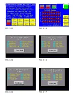
Страница 27: ...FIG 3 12 FIG 3 13 FIG 3 14 FIG 3 15 FIG 3 16 FIG 3 17 ...

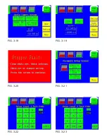
Страница 28: ...FIG 3 18 FIG 3 19 FIG 3 20 FIG 3 21 FIG 3 22 FIG 3 23 ...

Страница 29: ...n the Settings Screen a Under Product Weight Value _____________ b Over Product Weight Value ______________ Note You can also use the Auto Set button to automatically perform the settings function 4 Remove the product from the scale Place the scale in the RUN mode and drop the good product onto the scale The scale should rotate dropping the product in the ACCEPT feed direction If it rejected the p...

Страница 30: ...This page intentionally left blank ...

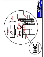
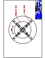
Страница 31: ...Chapter 4 Machine Adjustment Settings Rotary Drum Positioning Sensor Settings Accumulating Funnel Adjustments ...

Страница 32: ...he accumulator funnel holds the product above the drum so that product is not dropping onto the drum while previous product is being weighed or the drum is in motion The doors of the drum should close at the same time without banging Refer to drawings 4 3 for door speed adjustments and door position adjustments Refer to drawing 4 4 for door position setting Air pressure air pressure and speed cont...

Страница 33: ......

Страница 34: ......

Страница 35: ......

Страница 36: ......

Страница 37: ...Chapter 5 Trouble shooting Troubleshooting Checklist ...

Страница 38: ...ion Screen and set to MANL mode In this mode accum funnel should be open 1 No low air pressure 2 Leaking hoses or air cylinders 3 Product Sensor not sensing product 4 Incorrect mode of operation Accumulating funnel not functioning correctly or not at all 1 Check main individual power switch Plug in power cord 2 Replace fuse 1 on the module 3 Check breaker in main power box 4 Check cables behind I ...

Страница 39: ...Chapter 6 Replacement Parts Components Lists with Drawings ...

Страница 40: ...Level Report for 07 29 03 Seq No Item Description Quantity Assembly T FLIPR810 US 4000 Rotary Check Weigh Scale 1 TA CWR1000 Stand Assembly US 4000 1 2 TA CWR2000 Electronic Box Assy 1 3 TA CWR3000 Scale Head Assy 1 4 TA CWR4000 IOP Assy 1 5 TA CWR8000 Accumulator Chute US 4000 1 ...

Страница 41: ......

Страница 42: ...rials Top Level Report for 07 29 03 Seq No Item Description Quantity Assembly TA CWR1000 Stand Assembly US 4000 1 TP CWR1001 Base Assy US 4000 1 2 TP CWR1004 IOP Bracket 2 4000 1 3 TP CWR1005 EYE Bracket 1 4 TP 110764 Leveling Glide 4 5 TP 216134 Sensor Photoelectric 1 ...

Страница 43: ......

Страница 44: ...8141 Term Block Screw Clamp 15m 39 6 TP 208410 Terminal Blocks Direct Mo 4 7 TP 212229 7 pin circular male conn 1 8 TP 213359 Power supply 55W 5V 24V 12 1 9 TP 215341 Track MountRelaySocket Bas 2 10 TP 215384 Switch Rocker SPST 250V 1 11 TP 220511 PLC FPG C32T 1 12 TP 220513 PLC Communication Cassette 1 13 TP 501169 1 5 Phase Driver 1 14 TP 750015 Load Cell Digital Damped 1 15 TP 750015 1 Cable Lo...

Страница 45: ......

Страница 46: ...t for 07 29 03 Seq No Item Description Quantity Assembly TA CWR3000 Scale Head Assy 1 TA CWR3001 Rotary Drum Assy 1 2 TP CWR3008 Side Plate 2 3 TP CWR3009 Top Plate 1 4 TP CWR3010 Filler Plate 2 5 TP CWR3012 Guard Plate 1 6 TP 501169 2 5 Phase Stepper Motor 1 7 TP 504114 Bearing 7608 DLG 1 ...

Страница 47: ......

Страница 48: ...5 1 Rotary Short Shelf 1 5 TP CWR3005 2 Rotary Short Shelf 1 6 TP CWR3006 Motor Drum Plate 1 7 TP CWR3007 Support Drum Plate 1 8 TP 101103 Nut 8 32 Hex Mach Screw Pl 43 9 TP 101105 Nut 10 32 Hex Mach Screw 8 10 TP 102134 Washer 10 SAE Flat Zinc 8 11 TP 102153 Washer 8 Med Split Lock Z 43 12 TP 102154 Washer 10 Med Split Lock 8 13 TP 103195 Screw BHCS 8 32 x 5 16 40 14 TP 103217 Screw BHCS 8 32 x 3...

Страница 49: ......

Страница 50: ...39 Control Case I O P W 3 Fr 1 2 TP T1MD00039 1 Control Case IOP Back Plat 1 3 TP T1MD00039 3 IOP Front Plate Plain 1 4 TP 102134 Washer 10 SAE Flat Zinc 4 5 TP 102154 Washer 10 Med Split Lock 4 6 TP 103207 Screw BHCS 6 32 x 3 8 4 7 TP 103211 Screw BHCS 8 32 x 3 8 4 8 TP 111118 Bracket Swivel Ball Socke 1 9 TP 220350 Touch Screen 5 7 Display 1 10 TP 220350 1 Cable Touchscreen 1 ...

Страница 51: ......

Страница 52: ...t 2 15 TP 101141 Locknut Hex Nylon Insert 3 16 TP 102153 Washer 8 Med Split Lock Z 18 17 TP 102155 Washer 1 4 Med Split Lock 2 18 TP 103138 Screw SHCS 1 4 20 x 5 8 S 4 19 TP 103212 Screw BHCS 8 32 x 1 2 18 20 TP 103226 Screw BHCS 1 4 20 x 1 2 21 TP 103304 1 Screw Sock Shldr 1 4x5 8x 2 22 TP 103331 Screw Sock Shoulder 1 4 x 1 23 TP 107115 Bushing Flange 1 2ID x 5 4 24 TP 107321 Sleeve Bearing 1 4ID...

Страница 53: ......

Страница 54: ......

Отзывы: