Smart IP Strobe (IPSTROBE)
Advanced Network Devices • 3820 Ventura Dr. Arlington Hts.
IL 60004
Support:
•
847-463-223
7 •
www.anetdsupport.com
3
v2.2
INSTALLATION
The strobe assembly can mount to a 4”
square junction box as follows:
1.
Run Cat5 cable to the junction box,
and terminate the end, leaving
abo
ut 12” of slack
inside the box.
2.
Set the heads of the junction box
screws to protrude with
~1/8” of
space under each head.
3.
Open the strobe assembly by
removing the two screws at either
side of the top of the box.
4.
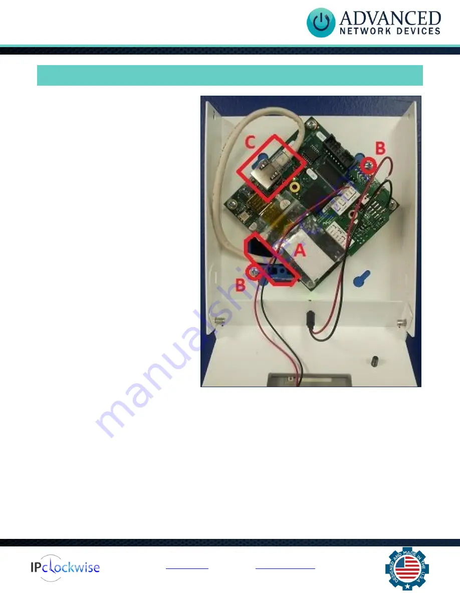
Feed the Cat5 cable through the
large 6-sided hole in the strobe box
at the bottom left (s
ee “A” in photo)
.
5.
Attach the strobe box to the junction
box by placing two of the diagonal
slotted holes over the protruding
screws (se
e “B” in photo)
. Tighten
the screws to firmly attach the
strobe box to the junction box.
6.
Plug the Cat5 cable into the main
circuit board in the location marked
“Ethernet Cable” (see “C” in photo)
.
Make sure the Cat5 connector snaps into the metal connector receptacle on the circuit board,
such that it won't disconnect when gently pulled.
7.
Stuff extra Cat5 cable back into the junction box cavity to minimize the amount of cable within
the strobe assembly.
8.
Fold up the front of the chassis and fasten in place using the two previously removed screws that
came with the strobe assembly.


