background image

4

2

8

10

4

5

6

9

1

7

4

Reviewing the Menus

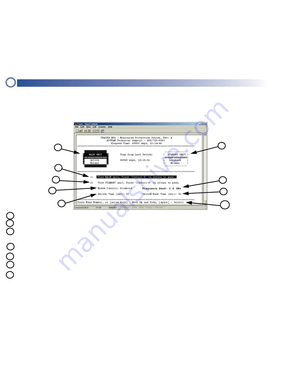
The TRACER MPS software interface consists of a single menu screen (shown below). Navigate through the available menu options 
using the up and down arrow keys. Alternately, the numbered menu options may be selected by entering the appropriate menu number 
displayed to the left of the option. Pressing the <space bar> activates the current menu selection. The TRACER MPS VT100 interface 
provides access to the MAIN and STANDBY TRACER unit menus (using menu options 1 and 2, respectively). Press <Ctrl + R> to exit the 
TRACER menus and return to the TRACER MPS menu screen. A brief description of the available menu options for the TRACER MPS 
follows the figure below.

Navigational Help

Status of MAIN 
TRACER system

Status of STANDBY 
TRACER system

4

Activates the menu system for the MAIN TRACER unit. This provides access to all configuration and status parameters.

5

Activates the menu system for the STANDBY TRACER unit. This provides access to all configuration and status parameters.

6

Configures the TRACER MPS for modem or terminal access. When connecting a VT100 terminal or PC with terminal software, 
select D

ISABLED

.To connect a modem to the TRACER MPS RS-232 interface, set this parameter to E

NABLED

. To disable the modem 

control, press <Ctrl + Z> three times.

8

Number of seconds the TRACER MPS waits (after a switch to the STANDY system) before attempting to restore MAIN operation.

9

Number of contiguous seconds the MAIN TRACER system must exhibit an alarm condition before the TRACER MPS switches to 
STANDBY operation.

10

Provides instructions for navigating through the menus using the arrow keys or entering the menu number and activating the 
highlighted menu by pressing the space bar.

7

Specifies the frequency band of the MAIN and STANDBY TRACER units as 5.8 GHz or 2.4 GHz. This menu setting should match 
the operational frequency of your TRACER systems, and must be manually configured by the user prior to operation.

Содержание TRACER Protection Switch

Страница 1: ...acts between the TRACER BBP or 4103 4203 and the TRACER MPS also needed for connecting the MPS to an external alarm monitoring system Antenna mounting hardware and feedline cable 21 to 63 VDC power so...

Страница 2: ...below each BBP T R A C E R MAIN STANDBY OUT NO COM NC MN COM SB IN ALARMS DC POWER RF ANTENNA TO DTE RS 232 MONITOR T1B T1A MAIN TRACER STANDBY TRACER MONITOR POWER MODULE USE COPPER CONDUCTORS ONLY M...

Страница 3: ...OR T1B T1A MAIN TRACER STANDBY TRACER MONITOR POWER MODULE USE COPPER CONDUCTORS ONLY OUT IN IN OUT B A B A MAIN STAND BY MANAGEMENT T1A T1B STANDBY UNIT VT100 Connection MAIN UNIT VT100 Connection 1...

Страница 4: ...tatus parameters 5 Activates the menu system for the STANDBY TRACER unit This provides access to all configuration and status parameters 6 Configures the TRACER MPS for modem or terminal access When c...

Страница 5: ...s labeled 3 and 4 below 2 Repeat Step 1 to connect the T1A and T1B interfaces of the STANDBY TRACER BBP to the STANDBY T1A and T1B interfaces RJ 45 of the TRACER MPS labeled 5 below MAIN UNIT T1B Inte...

Страница 6: ...labeled 1 below to the MAIN RF interface SMA con nector of the TRACER MPS labeled 2 below using a male N Type to male SMA cable 2 Connect the IF connector on the MAIN TRACER BBP labeled 4 below to th...

Страница 7: ...3 below T R A C E R MAIN STANDBY OUT NO COM NC MN COM SB IN ALARMS DC POWER RF ANTENNA TO DTE RS 232 MONITOR T1B T1A MAIN TRACER STANDBY TRACER MONITOR POWER MODULE USE COPPER CONDUCTORS ONLY OUT IN...

Страница 8: ...ovides the optional MIN Minor Alarm terminal block Connecting the MIN alarm contacts allows the TRACER MPS to perform a system switch when a minor alarm condition occurs Please refer to the TRACER 260...

Страница 9: ...e applied voltage in Volts As an example at 48 Volts the TRACER MPS would draw approximately 0 417 Amps peak 20 Watts 48 Volts 9 Pinouts MAIN STANDBY T1A T1B INTERFACES RJ 45 Pin Name Description 1 R...

Отзывы: