Quick Start
Guide
Overview
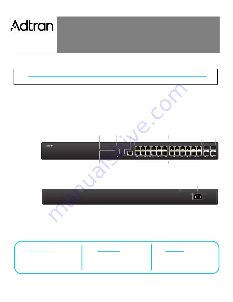
This quick start describes how to install, configure, and troubleshoot the NetVanta 1570-24-370W, Layer 3 Lite PoE+ Switch. Figures 1 and 2 show the
Front and Rear Panel layouts of the switch.
■
■
■
■
“Understanding the Status LEDs”
■
■
Figure 1. Front Panel Layout
Figure 2. Rear Panel Layout
WARNING!
f
Read all warnings, cautions, notes and installation instructions before installing or servicing this equipment.
NetVanta 1570-24-370W
SYSTEM
LNK/ACT/SPD
PoE
CONSOLE
USB
MODE/RESET
1
2
3
4
5
6
7
8
9
10
11
12
13
14
15
16
17
18
19
20
21
22
23
24
25
26
27
28
LINK/ACT/SPD
Mode LED
SYS
LED
CONSOLE
Port
10/100/1000
RJ-45 with PoE+
1G/10G
SFP+ Ports
PoE
Mode LED
MODE
Button
Port Status
LEDs
AC Line: 100-240V 50-60Hz
AC Line: 100-240V 50-60Hz
Power Connection
f
WARNING!
f
CAUTION!
g
NOTE
WARNING indicates a hazard which, if
not avoided, could result in death, injury
or serious property damage.
CAUTION indicates a hazard which, if not
avoided, could result in service interruption,
damage to the equipment, or minor property
damage.
NOTES inform the user of additional, but
important, information or features.
NetVanta 1570-24-370W
Layer 3 Lite PoE+ Switch
August 2022
617101574PF1-13A
P/N: 17101574PF1


