
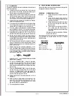


9.0 SPECIFICATIONS
INPUT/OUTPUT
INPUT SIGNALS
a. Contact 24 vdc@ 2 ma rating, N.O. or N.C.: specify
b. Voltage: Oto 12 vdc minimum, 30 vde maximum
c. Ramp Range: 0.1 second to 50 hours
d. Ramp hold and up/down command input
OUTPUT SIGNALS/OUTPUT DRIVE
AC Power
DC Power
a. 4-20 ma de
b. 10-50 ma de
c. 0-1 ma de
d. 1-5 vdc
0-1000 ohms max.
0-400 ohms max.
0-20,000 ohms max.
250 ohms
Z
out
0-900 ohms max.
0-350 ohms max.
0-18,000 ohms max.
250 ohms
Z
out
e. 0-10 vde
500 ohms
Z
out
500 ohms Z out
Or zero based in the same ranges. Other voltage and currents
optional.
PERFORMANCE
a.
Calibrated Accuracy:
± 0.1 %
b.
Linearity:
± 0.1 % maximum,± 0.04% typical
c.
Repeatability:
± 0.05% maximum
d.
Temperature Stability:
± 0.01%/
°
F maximum,
± 0.004%/
°
F typical
e.
Load Effect:
± 0.01% zero to full load
f.
Output Ripple:
10 mv PIP maximum
g.
Response Time: As
calibrated
h.
Temperature Range:
0
°
to 140
°
F (-18
°
to 60
°
C) operating
-40
°
to 185
°
F (-40
°
to 85
°
C) storage
i.
Power Supply Effect:
± 0.05% for a± 10% power variation
Note: All accuracies are given as a percentage of span
POWER
a. 115 vac: ± 10%, 50/60 Hz, 3 watts, 0. 7 Pf (standard)
b. 24 vdc: ± 10% isolated, 3 watts (Option P2)
c. 48 vdc: ± 10% isolated, 3 watts (Option P3)
d. 125 vdc: Nominal (105-140 vdc) isolated, 3 watts (Option P4)
e. 230 vac: ± 10%, 50/60 Hz, 3 watts, 0.7 PF (Option PS}
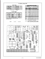
10.0 OUTLINE & MOUNTING
1------ 7.0in.
(178mm)
0.234
in. diameter
2 places (clearance for 110 screw} 0.234 in. diameter 2 places {clearance for #10 screw)
,,,,,,
,,.. ..
,, ,,,,
,,,,,,
,, .. ,,
,, .. ..
,,,, ,, .,
.. .. ..
,,
.,
--
--
-------------------
r::�
c
.�!:,------
One 7/8 in. diameter hole for 1/2 in. conduit
(22.2mm)
(6mm)
(6mm)
Holes for up to
8 - Adjustment
Controls
4 Screws,
remove to
pull out
module if
8_50 �- required
(216mm)
Allow 1.5'
(38mm)for
-4-
Holes for up to
8 - Adjustment
Controls
Second terminal
block-option
Allow 2.8"
(71mm)for
side by side
mounting without
front covers.
190-A-000029-0