


6.0 CALIBRATION
To perform a calibration check or re-calibration of the instrument
follow this procedure.
A. Carefully remove the instrument from the housing to
gain access to the inside components observing all
normal safety and equipment precautions.
B. Make sure the unit l/0 wiring is properly connected and
that the correct power source per the label is also
connected. The instrument must be at normal power
for a minimum of 2 minutes before proceeding to C.
C. Connect the input contacts for Up-Down and Ramp
Hold to the appropriate inputs.
D. The output may be monitored either as a direct voltage
for a voltage output signal or as a current that can be
represented as a voltage across a resistor shunt.
E. Turn the multiturn potentiometers marked UPRATE
and DOWN RATE fully CW. This sets the Ramp rates
at the high value for t he particular jumper configuration.
F. Temporarily set jumpers J14, J15, J16 and J18 to
position 8 to set the output response at the fastest rate.
G. Set the input contacts to drive the output down to
minimum value and adjust the multiturn potentiometer
marked ZERO to provide the minimum calibrated output
(e.g.) 4.00 ma± 0.01 ma de.
H. Set the input contacts to drive the output to maximum
value and adjust the multiturn potentiometer marked
SPAN
to provide the maximum calibrated output (e.g.)
20.00 ± 0.01 ma de.
I. Repeat steps G and H until within calibration;± 0.1 %.
J. From the RAMP TIME SELECTION TABLE Section
8.0 look up the value of N corresponding to the smaller
of the UP RAMP TIME and DOWN RAMP TIME and
calculate the frequencies;
fup = 4096N Hz,
fdown = 4096N
Tup
Tdown Hz
where T and T d<lwn are UP RAMP TIME and DOWN
RAMP TiME in seconds.
K.
To set the UP-RAMP TIME: connect a frequency
counter from pin 13 of
zg
to Term #5; set the input
contacts for UP-RAMP mode and adjust the multiturn
potentiometer marked UP-RATeto provide a frequency
equal to f up.
L. To set the DOWN-RAMP TIME: connect a frequency
counter from pin 13 of
zg
to Term #5; set the input
contacts for DOWN-RAMP mode and adjust the
multiturn potentiometer marked DOWN-RATE to
provide a frequency equal to f down.
M.
Repeat steps Kand L until within calibration;± 0.1 % of
frequency.
N.
Note the jumper configuration corresponding to the
value of N in the table and set jumpers J14, J15, J16
and J18 accordingly. This step provides the actual
desired UP
RATE
and
DOWN RA
TE.
0. This completes the calibration.
7.0 FIELD TROUBLE SHOOTING GUIDE
This section offers a simple, first level trouble-shooting aid for
an apparent instrument malfunction.
SYMPTOM
No output
CORRECTIVE ACTION
1. Check the input and output connections
carefully.
2. Check that the
power
supply polarity is
correct and that
power
is present on the
instrument terminals.
3. Check that the input contacts are correct
and that they change their state from
open to close.
4. If the output is a current signal (4-20 ma,
etc.), make sure the output loop is
complete and thatthe correct meter range
is selected.
All external checks are complete. Problem
seems to be internal.
The following information is provided for a qualified technician
or serviceman as check points for use in internal
troubleshooting.
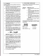
CHECKPOINT/
COMPONENT
(across)
C20
Term 1 (-) to Ei+)
Term 1 (-) to E
1
(+)
Term 1(-)to pin 19 of Z
4
(+)
VOLTAGE/RANGE
26 ± 4 vdc
12 ± 0.6 vdc
-12 ± 0.6 vdc
9.4± 0.5 vdc
-2-
190-A-000029-0