Adtech Q2BYG403MD Скачать руководство пользователя страница 14


Q2BYG403MD Driver User’s Manual 

-13- 

Chapter IV. FAQ   

4.1 Motor selection   

Q2BYG403MD is suitable for 4, 6, 8-wire two phase hybrid step motor. 
However, to make the motor have optimized running effect, it is usually 
required to select appropriate motor to match the Driver.   

(1) It is known from the torque-frequency characteristics of the step 

motor that the output torque decreases along with the increase of 
motor speed. Generally, at light load, the maximum working speed is 
below 15 rev/sec, and at heavy load, the maximum working speed is 
about 10 rev/sec. If the system has a higher requirement on speed, 
please select servo motor.   

(2) If step motor is selected, please select the model of appropriate torque 

according to the load.   

(3) During working, it is allowed to change the system transmission ratio 

through gear box and synchronous belt, and thus adjust the 
relationship between output torque and load speed.   

(4) Increase the supply voltage of the step motor to improve the working 

speed of the motor; increase the working current of the step motor to 
improve the torque of the motor; increase the subdivisions of the step 
motor to improve the precision of motor, and also improve the 
stability of the motor, and reduce vibration and noise.   
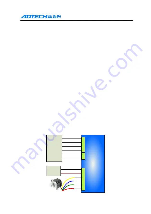
4.2 Typical wiring   

The control signal wiring of the controller and Driver can be one of the 
three wiring modes shown in 3.3.2. The power supply and motor wiring 
is shown below:   

Q2BYG403MD

Driver

DR+

DR-

PU-

PU+

EN+

EN-

DC-

DC+

B-

B+

A-

A+

Cotroller

DC power 

supply

24-40VDC


Содержание Q2BYG403MD

Страница 1: ...ri iv ve er r U Us se er r s s M Ma an nu ua al l Add F 5 Bldg 27 29 Tianxia IC Industrial Park Yiyuan Rd Nanshan District Shenzhen Tel 0755 26099116 Fax 0755 26722718 616 Postal code 518052 E mail e...

Страница 2: ...ndividual are prohibited This manual doesn t contain any assurance stance or implication in any form Adtech and the employees are not responsible for any direct or indirect data disclosure profits los...

Страница 3: ...cal specification and electrical installation standard during the installation The Driver must be grounded properly and the cross sectional area of the grounding cable should be at least 1 25mm2 Do no...

Страница 4: ...2 2 Features Allow driving 4 6 8 wires two phase step motor Ultra low vibration noise Internal software uses micro segmentation technology which can obtain high segmentation effect in low speed low se...

Страница 5: ...point 18VDC Phase current A 1 2 1 6 2 0 2 4 2 8 3 0 3 6 4 2 Subdivisions 1 2 4 8 16 32 64 128 256 5 10 25 50 100 200 Control mode Pulse direction Type of protection circuit Undervoltage overvoltage a...

Страница 6: ...ow voltage level 0 0 5V high voltage level 4 5V pulse width 1 5us EN EN Enable control signal Used to enable release motor EN is connected to 5V EN is grounded the Driver will cut off the current of t...

Страница 7: ...itter terminal 3 SCI receiver terminal RXD Serial data receiver terminal 4 NC Reserved 5 5V power supply grounding GND Power point 4 Driver status indicator The green LED is power indicator When the p...

Страница 8: ...s differential interface circuit builds in high speed optocoupler the receiving frequency is higher than similar products interface is highly compatible and anti jamming capacity is strong especially...

Страница 9: ...ted to 12V R is 1K when VCC is connected to 24V R is 2K 2 Common cathode wiring when VCC is connected to 5V R is short connected when VCC is connected to 12V R is 1K when VCC is connected to 24V R is...

Страница 10: ...ection If the Driver and motor are connected in different modes the motor running will have significantly different effect Generally the supply voltage of the Driver determines the high speed performa...

Страница 11: ...available Serial mode has large torque at low speed but it can t rotate fast as connected to center tap and the current should be set to 70 of the rated current center tap mode has high speed performa...

Страница 12: ...inaccurate motor positioning instable system and other faults 3 If one power supply is provided to several Drivers it is required to connect them in parallel rather than in chain 4 Do not insert or re...

Страница 13: ...F OFF 4 OFF ON OFF OFF 8 ON ON OFF OFF 16 OFF OFF ON OFF 32 ON OFF ON OFF 64 OFF ON ON OFF 128 ON ON ON OFF 256 OFF OFF OFF ON 5 ON OFF OFF ON 10 OFF ON OFF ON 25 ON ON OFF ON 50 OFF OFF ON ON 100 ON...

Страница 14: ...lected please select the model of appropriate torque according to the load 3 During working it is allowed to change the system transmission ratio through gear box and synchronous belt and thus adjust...

Страница 15: ...put Adjust the pulse signal Subdivision has error Reset the subdivisions Motor load is too high Change the motor or increase the current Position is inaccurate Motor wire bad contact Check and connect...

Отзывы: