Motor3
(
J3
)
Blue
BK
BK
Yellow
5
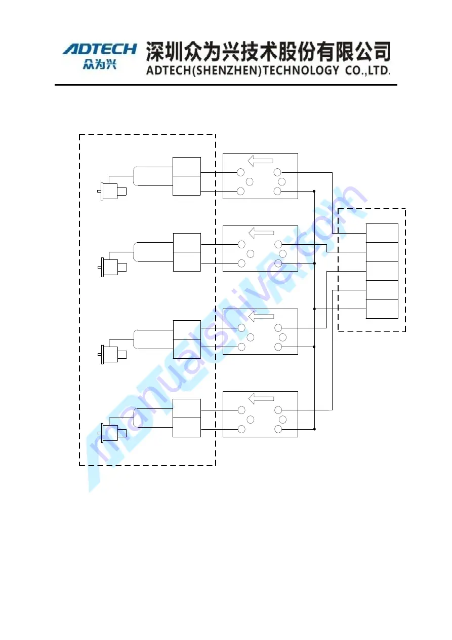
Definition of brake(17bit absolute encoder
of Panasonic)
Wiring diagram of brake wiring for ADTECH robot
6
Motor2
(
J2
)
Blue
BK
BK
Yellow
5
6
Blue
BK
BK
Yellow
5
6
Motor1
(
J1
)
Motor4
(
J4
)
Blue
BK
BK
Yellow
5
6
R
B
Y/G
W
W
R
B
Y/G
W
W
R
B
Y/G
W
W
R
B
Y/G
W
W
Y/G
Y/G
Y/G
Y/G
GrayRed
GrayBlack
WhiteRed
WhiteBlack
OrangeRedRed
Internal 24V
Relay4
Relay3
Relay2
Relay1
Adapter plate of brake
IO of 16Core cables
For practical application, you must finish brake wiring based on the robot used
firstly. Then configure brake port, please refer to
【
Teaching Pendent Operation
】
.
Содержание ADT-RC400
Страница 1: ...ADTECH Robotic Drive System ADT RC400 User Manual Electrical Wiring ...
Страница 11: ...X Power cord must be used with the specified wire Prone to fire and failure ...
Страница 20: ...19 Peripheral Devices SCARA Robot FlexPendant IO Board QC400 Controller Figure 2 1 System Configuration ...
Страница 45: ......


