background image

ADT-09 Series Motion Control Card 


http://www.adtechcn.com 


  56


22 

IN27 

General input 

23 

IN28 

General input 

24 

IN29 

General input 

25 

IN30 

General input 

26 

IN31 

General input 

27 

IN32 

General input 

28 

IN33 

General input 

29 

IN34 

General input 

30 

IN35 

General input 

31 

IN36 

General input 

32 

IN37 

General input 

33 

IN38 

General input 

34 

IN39 

General input 

35 

IN40 

General input 

36 

IN41 

General input 

37 

+24V GND 

24V power grounding 

38 

+24V VCC   

+24V power output (can’t be connected to external 24V+) 

Note: Both digital input and output signals are active low.


5.4.3.


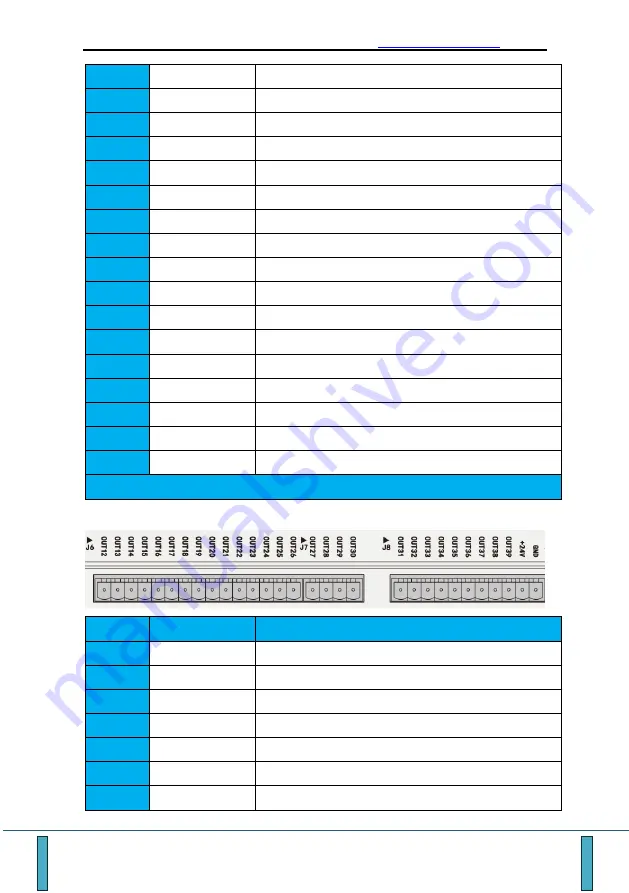
Definitions of J6/J7/J8 output ports 


Pin No. 

Pin definitions 

Function 

OUT12 

Output control signal, opto-isolated output, active low


OUT13 

Output control signal, opto-isolated output, active low


OUT14 

Output control signal, opto-isolated output, active low


OUT15 

Output control signal, opto-isolated output, active low 

OUT16 

Output control signal, opto-isolated output, active low


OUT17 

Output control signal, opto-isolated output, active low


OUT18 

Output control signal, opto-isolated output, active low


Содержание ADT-09 Series

Страница 1: ...ADT 09 Series Motion Control Card http www adtechcn com 1 ADT 09 Series Motion Control Card User Manual ADT 8949C1 H1 ADT 8969C1 H1 ADT 8989C1 H1 ...

Страница 2: ... the imitation copy transcription and translation by any organization or individual are prohibited This manual doesn t contain any assurance stance or implication in any form Adtech and the employees are not responsible for any direct or indirect data disclosure profits loss or cause termination caused by this manual or any information about mentioned products in this manual In addition the produc...

Страница 3: ...T 9160 TERMINAL BLOCK OF ADT 8969 8 2 2 4 ADT 9180 TERMINAL BLOCK OF ADT 8989 8 2 2 5 ADT D62GG DATA TRANSMISSION LINE 8 2 3 SYSTEM STRUCTURE DIAGRAM 9 2 4 STEPS TO INSTALL CONTROL CARD 9 2 4 1 BOARD INSTALLATION 9 2 4 2 ONE CLICK SETUP OF DRIVER 9 2 4 3 MANUAL INSTALLATION OF DRIVER 12 2 4 4 COMMUNICATION SETUP 18 2 4 5 MOTORS AND DRIVERS 18 2 4 6 TERMINAL BOARD CONNECTION AND POWER SUPPLY 19 2 4...

Страница 4: ...LECTRICAL SPECIFICATIONS 37 3 7 WORK ENVIRONMENT 38 CHAPTER 4 BASIC DEBUGGING 39 4 1 ESTABLISHING A COMMUNICATION 40 4 2 BASIC PARAMETERS 42 4 3 IO CONTROL 44 4 4 AXIS INFORMATION MONITORING 45 4 5 MULTI AXIS MOTION 46 CHAPTER 5 APPENDIXES 48 5 1 COMMON PROBLEMS FOR DRIVER INSTALLATION 48 5 1 1 THE CONTROL CARD CANNOT BE DETECTED AND THE DRIVER CANNOT BE INSTALLED NORMALLY 48 5 2 CONTROL CARD INIT...

Страница 5: ...ERMINAL BLOCK 55 5 4 1 25 PIN DB PORT DEFINITION 55 5 4 2 DEFINITIONS OF J2 J3 J4 J5 INPUT PORTS 55 5 4 3 DEFINITIONS OF J6 J7 J8 OUTPUT PORTS 56 5 4 4 J9 DA PORT DEFINITION 57 5 5 WIRING INSTRUCTIONS OF ADT 8949G1 WITH ADT 9192 TERMINAL BLOCK 58 5 5 1 DEFINITION OF 25 PIN DB PORT 58 5 5 2 SIGNAL DEFINITION OF J2 INTERFACE 58 5 5 3 J3 INTERFACE SIGNAL DEFINITION 59 5 6 PRECAUTIONS 61 5 7 DOCUMENT ...

Страница 6: ...ical interpolation would produce arcs in arbitrary spatial planes as well as spherical arcs It is useful for simplifying the complex graphics By using 33 3M PCI communication up to 10 control cards can be expanded on one PC Furthermore with the PC platform complex occasions such as distributed motion control can be realized 09 Series PCI based pulse motion control card is suitable for control occa...

Страница 7: ...sion The adaptive speed model guarantees both high speed and high precision which satisfies needs of high precision and high efficiency in the industry 3 Hardware can also be upgraded to create the maximum value Use of the FPGA dual DSP multi embedded system and the key performance is guaranteed by hardware level real time processing The upgrade of the hardware enables the control card to be downw...

Страница 8: ...6 6 8 8 Encoder feedback frequency 4MHz DIP switch 0 9 Platform performance A9 dual core Universal digital input 42 Universal digital output 24 Servo enable output 4 4 6 6 8 8 Alarm clear output 4 4 6 6 8 8 Servo alarm input 4 4 6 6 8 8 Fast input port 2 Fast output port 2 Control Function Hardware Signal Hardware emergency stop Limit signal stop Mechanical origin stop Encoder Z phase signal stop ...

Страница 9: ...ation Plane arc interpolation Space arc interpolation Spiral interpolation Synchronous follow Change the drive speed in motion Change the target position in motion High speed IO High speed position latch 1D 2D 3D High speed position comparison Advanced Cache Control Speed look ahead Cache interpolation capacity 10000 10000 10000 Cache IO event capacity 1000 1000 1000 Cache output control Cache del...

Страница 10: ... DOS and Windows 1 4 Industry Applications Machine vision automatic test equipment AOI Biological medical automatic sampling equipment Cutting equipment diamond cutter sponge cutting machine Dispensing industry Semiconductor packaging industry Bonder Advertising industry CNC bending machine Packaging and printing equipment printer pad printer Engraving equipment Industrial robot equipment PCB proc...

Страница 11: ...969 series Product Model Name Description Dimension Parameters ADT 8969C1 ADT 8969H1 Motion control card ADT 8969C1 ADT 8969H1 135 mm 110 mm 1 Wiring board ADT 9160 248 mm 154 mm 30 mm 1 Data cable ADT D62GG 1 5 M 1 User s Manual Instructions 1 User CD Electronic files such as SDK examples and Instructions 1 2 1 3 ADT 8989 series Product Model Name Description Dimension Parameters ADT 8989C1 ADT 8...

Страница 12: ... 09 Series Motion Control Card http www adtechcn com 7 2 2 Installation dimensions 2 2 1 09 series motion control card 2 2 2 ADT 9140 terminal block of ADT 8949 Dimensions chart of ADT 9140 terminal block ...

Страница 13: ... http www adtechcn com 8 2 2 3 ADT 9160 terminal block of ADT 8969 Dimensions chart of ADT 9160 terminal block 2 2 4 ADT 9180 terminal block of ADT 8989 Dimensions chart of ADT 9180 terminal block 2 2 5 ADT D62GG data transmission line ...

Страница 14: ... the 09 Series Motion Control Card is properly installed the green LED on the back of the board will light up which means that the FPGA chip is running normally When the red LED on the front will light up it means that the board is powered normally If the above LED indicators do not work there may be a hardware failure occurred in the board Please return it to the factory for repair or replacement...

Страница 15: ...ol card not detected as shown in the figure below appears please check that the control card is still plugged in and try again 4 The computer can detect the card by displaying the following screen 5 Click Next you can then enter the following screen 6 Select the installation path it is recommended to choose the default installation path and click Next ...

Страница 16: ...w adtechcn com 11 7 Click Next 8 Click Install and wait for the installation process to complete 9 After the installation is completed checking Run VC DEMO and Finish you can then test the driver installation which is shown in the figure below ...

Страница 17: ...known PCI device then can the driver be installed As for the XP system the wizard for new hardware will pop up automatically after startup or an unknown PCI device will be found in the device manager Unknown PCI devices are found in the Device Manager for WIN7 systems The number of unknown PCI devices should be no less than the number of boards installed in the current system ...

Страница 18: ...evice manager it means that there s no board information detected by the current operating system Possible problem descriptions and solutions can be found in the 5 1 Driver Installation FAQs 2 Driver installation under Windows XP When the system starts if the PCI detects an unknown hardware device the prompt below appears Select in above figure to pop up the following screen Select in above figure...

Страница 19: ...DT 09 Series Motion Control Card http www adtechcn com 14 Click Browse select CD Development Kits Drivers Control Card Drivers to locate the driver file path and click Next to pop up the following screen ...

Страница 20: ...s on Win7 Insert the control card into PCI slot right click My Computer and select Properties to enter Device Manager as shown below Expand Other devices select PCI Bridge Device Different systems may have different unknown device names and right click as shown below In the popup dialog box click Update Driver Software to show the following dialog box ...

Страница 21: ...eries Motion Control Card http www adtechcn com 16 Select the option Browse my computer for driver software Click the Browse button to specify the path for the driver and select the appropriate system file Next ...

Страница 22: ...ww adtechcn com 17 Always install this driver software Follow the installation instructions until installation is complete The ADT 09 Series control card has been installed by this time and the device manager will update of the device details ...

Страница 23: ...em to load the PCI driver If you run the control card application directly for the first time by double clicking the control card initialization will then be failed Therefore after the first installation is completed right click the control card application i e VC demonstration program DEMO EXE and select Run as administrator A program as shown below then start the application by double clicking 2...

Страница 24: ...perly connected to the board and terminal board J1 and the board is powered on the POWER green indicator in the lower left corner of the terminal board will work indicating that the terminal board and the board are connected normally when the external 24V power supply supplies power to the terminal board the RUN green indicator on the lower left corner of the terminal block will flash which means ...

Страница 25: ...vers Connect the terminal board to the driver based upon actual needs 4 6 8 sets of drivers can be connected to the terminal board AXIS is a 25 pin DB port For terminal definition refer to 3 1 1 25 pin DB port definition For the servo driver you can refer to 5 3 Common Servo Wiring Diagram ...

Страница 26: ... External input active low and does not support two wire sensor connection It is usually used as a servo alarm input Y axis Z axis A axis B axis C axis D axis E axis corresponding to IN1 IN2 IN3 IN4 IN5 IN6 IN7 3 EXT_OUT1 Output control signal opto isolated output active low It is usually used as servo enable Y axis Z axis A axis B axis C axis D axis E axis corresponding to OUT3 OUT5 OUT7 OUT9 OUT...

Страница 27: ... input negative It can be used as a normal input point corresponding to the sample program input point IN60 Y axis Z axis A axis B axis C axis D axis E axis corresponding to IN61 IN62 IN63 IN64 IN65 IN66 When the IN67 is used as a normal input point please refer to 3 4 Digital Input Connection for wiring mode and the encoder signal is used as a graphic description of the general input 7 VCC 5V pow...

Страница 28: ... negative signal 23 XPU X axis pulse positive signal 24 GND 5V power grounding 25 NC 3 1 2 15 pin Hand Wheel Port Definition CN9 CN9 wiring diagram wiring definition ADT CNC6A Handwheel Box Wiring Definition Pin No Pin Definitions Function 1 IN50 Hand wheel general input for gear X1 with ADT CNC6A hand held box 2 IN52 Hand wheel general input for gear X10 with ADT CNC6A hand held box 3 IN54 Hand w...

Страница 29: ...ox 11 IN55 Hand wheel general input for switching to Z axis with ADT CNC6A hand held box 12 IN57 Hand wheel general input for switching to A axis with ADT CNC6A hand held box 13 IN59 Hand wheel general input for switching to B axis with ADT CNC6A hand held box 14 HB Hand wheel output phase B signal 15 GND_5V_EXT 5V power output grounding Note Before using the hand wheel please confirm that the INC...

Страница 30: ...al input 8 IN15 ALT A negative limit signal can be used as general input 9 IN16 XHM X origin signal alias STOP0 can be used as general input position latch 10 IN17 YHM Y origin signal alias STOP0 can be used as general input position latch 11 IN18 ZHM Z origin signal alias STOP0 can be used as general input position latch 12 IN19 AHM A origin signal alias STOP0 can be used as general input positio...

Страница 31: ...ias STOP0 can be used as general input position latch ADT 9140 60 for general input 11 IN30 DHM D origin signal alias STOP0 can be used as general input position latch ADT 9140 60 for general input 12 IN31 EHM E origin signal alias STOP0 can be used as general input position latch ADT 9140 60 for general input 13 INCOM2 IN20 IN31 input public terminal access DC12 24V J4 1 IN32 General input can be...

Страница 32: ...icated output 3 OUTCOM OUT16 OUT17 output public terminal access DC12 24VGND J7 1 EX24V OUT18 OUT29 output port power DC24V input 2 OUT18 Output control signal opto isolated output active low 3 OUT19 Output control signal opto isolated output active low 4 OUT20 Output control signal opto isolated output active low 5 OUT21 Output control signal opto isolated output active low 6 OUT22 Output control...

Страница 33: ...7 OUT34 Output control signal opto isolated output active low 8 OUT35 Output control signal opto isolated output active low 9 OUT36 Output control signal opto isolated output active low 10 OUT37 Output control signal opto isolated output active low 11 OUT38 Output control signal opto isolated output active low 12 OUT39 Output control signal opto isolated output active low 13 OUT40 Output control s...

Страница 34: ...tion PUCOM is the 7th pin of the 25 pin DB connector 5V power output To enhance the anti interference ability of the common anode connection it is recommended to connect the DB side 5V GND Pin 10 13 20 21 24 to the driver terminal ground wire PUCOM Step motor driver PU CW DR CCW PU PU DR DR Below is independent connection of pulse and direction signal Differential connection is recommended due to ...

Страница 35: ...ed pulse port of the differential output the Pin 13 of the 25 pin DB connector pin in the control card must be connected to the ground wire of the servo pulse output port 3 3 Connecting encoder input signal OPEN CONNECT Output Encoder Wiring Diagram as below For 5V power R can be omitted for 12V power R 1 kΩ for 24V power R 2 KΩ Encoder ECA ECA B B A A 5V ACC 5V GND ...

Страница 36: ...he figure below for which the switch polarity is no longer needed to be considered IN8 IN9 IN10 IN11 IN12 IN13 IN14 IN15 IN16 IN17 IN18 IN19 INCOM1 J2 DC24V Mechanical switch connection The figure below shows the two wire sensor connection The polarity of the two wire sensor must be considered In general the ground line is in blue and output line is brown The input port IN0 IN5 in the 25 pin DB po...

Страница 37: ...t wire Grounding wire The three wire sensor is connected as shown in the figure below The polarity of the three wire sensor must be considered The colors corresponded to the polarity is provided in the instructions for the corresponding three wire sensor IN8 IN9 IN10 IN11 IN12 IN13 IN14 IN15 IN16 IN17 IN18 IN19 INCOM1 J2 DC24V Three wire sensor connection Three wire sensor Out Grounding wire ...

Страница 38: ...http www adtechcn com 33 When the AB phase signal of encoder is used as a universal input point Taking X axis is taken as an example with its wiring method shown below The K1 K2 K3 in the figure are connected using the mechanical switch ...

Страница 39: ...ng If the current drive capability is insufficient an external relay can be used for current expansion and the follow current protection diode shall also be connected Taking OUT18 as an example The general electromagnetic relay of output port drives is connected as below The polarity of the electromagnetic relay coil is not required to be considered if special instructions are provided OUT18 OUT19...

Страница 40: ...O relay must be used as shown in the figure below J7 24VEX OUT18 OUT19 OUT20 OUT21 OUT22 OUT23 OUT24 OUT25 OUT26 OUT27 OUT28 OUT29 OUTCOM Current expansion connection of electromagnetic relay DC24V High current electrical equipment Electromagnetic relay coil External VCC power supply External GND power supply ...

Страница 41: ...y the output port of the solid state relay is connected Pay attention to the polarity of the control terminal of the solid state relay J7 24VEX OUT18 OUT19 OUT20 OUT21 OUT22 OUT23 OUT24 OUT25 OUT26 OUT27 OUT28 OUT29 OUTCOM Solid state relay connection DC24V Solid state relay INPUT LOAD ...

Страница 42: ...Alarm clear output channel 25 pin DB port 1 channel for each axis opto isolated Output type NPN open collector 12 24V DC the single channel maximum output current of common output port 1A and single channel maximum output current of 25 pin DB port is 50 mA Count input Channel 4 6 8 AB phase encoder input all opto isolated Maximum counting frequency 4MHz Input voltage 5V High level 4 5V Low level 1...

Страница 43: ...ADT 09 Series Motion Control Card http www adtechcn com 38 3 7 Work environment Working temperature 0 60 C Storage temperature 20 80 C Working humidity 20 95 Storage humidity 0 95 ...

Страница 44: ...lopment reference for programmers The user interface and operation of sample application under each platform are essentially the same The basic debugging process of the 09 Series 8 axis Motion Control Card is described below by taking the VC sample application as an example to After locating the VC sample program DEMO09 exe right click to choose Run as administrator After locating the VC sample pr...

Страница 45: ...rol is required run it at low speed first then high to prevent device fault or damage due to operational errors during debugging 4 1 Establishing a communication The communication between the PC and the control card can be the initialization of the control card which can be established by debugging the control card initialization of the software You can try to establish communication between the P...

Страница 46: ...8 axis motion control card and the property page will intelligently disable the No 9 12 axis and will intelligently read the emergency stop signal mode of current control card as well as the default basic parameter of axis 1 8 which will be displayed in the corresponding parameter drop down box control The remaining property pages will also open 1 8 axis data control and read default parameters fo...

Страница 47: ...tings of the peripherals Only they match with peripheral parameters can the drive control be made in right accuracy and consistent direction Programming mode Generally there are two programming modes for each axis of the control card one is mm unit programming mode based on the pulse equivalent and the other is pulse based unit system programming mode The difference between the two programming mod...

Страница 48: ... the basic parameter attribute is the current actual configuration that is read from the control card and each axis and that is also the default configuration of the control card and each axis In this mode only the non debugging stage of the control card function verification will be performed that is the control card will not be connected to the peripheral during trial stage Do not change the def...

Страница 49: ...ent control card can be found on the property page IO Control Take the 4 axis motion control card as an example This panel monitors all input output states of the ADT 09 motion control card in real time It is necessary to verify hardware input signals of the Function Port panel one by one including hardware positive negative limit STOP0 and so on In the case of wiring support the encoder Z phase s...

Страница 50: ...n actual position current speed drive status stop information and target position information of all axes available of the current control card It also offers convenient monitoring of critical hardware signals for the debugging process Meanwhile the panel offers information such as the current speed drive status interpolation margin etc of the interpolation axis of 09 Series Motion Control Card By...

Страница 51: ...f speed and location in the panel is in pulse pulse s and pulse s In the position mode the relative position is the displacement of the target position relative to the current location and the absolute position is the target position is a displacement point in relative to 0 in coordinate position To verify the asymmetric acceleration deceleration effect you can enable the deceleration setting by c...

Страница 52: ...formation when the driving is finished and the position measurement after the driving is done The basic debugging of the control card has been verified at this time Where there is no abnormality found in the above process the control card hardware is correctly connected and the function is effective For the rest of the functions refer to the introduction of other functions in the 09 Series Motion ...

Страница 53: ...hich may vary depending on the system version 2 Check that the board and slot are in good contact When the control card is powered on a RED indicator will light on the front of the board If the board is powered on improperly or the system still cannot detect the board after normal power on it is then recommended to shut down and take out board and clear the dirt on gold finger of the control card ...

Страница 54: ...ded solutions are listed below 5 2 1 WinIO initialization failed Error Code 9 Possible cause Run the sample application not as an administrator Solution 1 Close the sample application currently run by right clicking and choose to Run as administrator 2 Close the sample application currently run by right clicking Properties Compatibility Privilege Level and run this program as an administrator 3 Up...

Страница 55: ...bled and the device manager has detected the motion control card of the specified model Possible cause 1 The control card driver is not installed properly 2 Run the sample application not as an administrator Recommended solution 1 Uninstall and reinstall the motion control card driver When uninstalling locate the specified control card device through the device manager Then right click and uninsta...

Страница 56: ...requency is 0 500 Kpps command pulse input applies the optocoupler input mode usually when the pulse frequency is 0 4Mpps the command pulse input uses private input mode of the long distance driver When the pulse frequency requirement is below 500 Kpps the optocoupler input mode is recommended Different command pulse input modes correspond to different pulse direction signal input terminals of the...

Страница 57: ... 4 OA 5 OB 6 OB 7 OZ 8 OZ 16 DR 15 DR 14 PU 13 PU 23 5V GND 50 COM 36 A CLR Pulse frequency is 0 500Kpps PE Driver CN1 Pin Definitions PIN 24 OUT COM 25 OUT COM 39 ALM 37 SRV ON 3 OA 4 OA 5 OB 6 OB 7 OZ 8 OZ 26 DR 27 DR 28 PU 29 PU 23 5V GND 50 COM 36 A CLR Pulse frequency is 0 4Mpps Note 1 When the pulse frequency is 0 500Kpps the driver CN1 terminals DR DR PU PU correspond to terminals 16 15 14 ...

Страница 58: ...PE Driver CN1 Pin Definitions PIN Pulse frequency is 0 4Mpps 36 ALM 41 OUT COM 37 ALM 29 SRV ON 21 OA 22 OA 48 OB 49 OB 23 OZ 24 OZ 47 SIGNH2 46 SIGNH1 45 PULSH2 44 PULSH1 13 GND 7 COM 37 A CLR Note 1 When the pulse frequency is 0 500Kpps the CN1 terminals SIGN1 SIGN2 PULS1 and PULS2 of the driver correspond to terminals 5 6 3 and 4 respectively that is the command pulse input mode is the optocoup...

Страница 59: ...nnector Pin Definitions Driver CN1 Pin Definitions PIN PIN Pin Definitions 1 24V GND 2 IN0 3 OUT1 17 ECA 4 ECA 18 ECB 5 ECB 19 ECZ 6 ECZ 9 DR 22 DR 23 PU 11 PU 13 5V GND 14 24V VCC 15 OUT0 46 47 COM 42 EMG 48 ALM 15 SRV ON 4 OA 5 OA 6 OB 7 OB 8 OZ 9 OZ 35 SING1 36 SING2 10 PULS1 11 PULS2 3 5V GND 20 21 COM 19 A CLR PE ...

Страница 60: ...used as general input 7 IN12 ALT A positive limit signal can be used as general input 8 IN13 ALT A negative limit signal can be used as general input 9 IN14 BLT B positive limit signal can be used as general input 10 IN15 BLT B negative limit signal can be used as general input 11 IN16 CLT C positive limit signal can be used as general input 12 IN17 CLT C negative limit signal can be used as gener...

Страница 61: ...4V VCC 24V power output can t be connected to external 24V Note Both digital input and output signals are active low 5 4 3 Definitions of J6 J7 J8 output ports Pin No Pin definitions Function 1 OUT12 Output control signal opto isolated output active low 2 OUT13 Output control signal opto isolated output active low 3 OUT14 Output control signal opto isolated output active low 4 OUT15 Output control...

Страница 62: ...solated output active low 19 OUT30 Output control signal opto isolated output active low 20 OUT31 Output control signal opto isolated output active low 21 OUT32 Output control signal opto isolated output active low 22 OUT33 Output control signal opto isolated output active low 23 OUT34 Output control signal opto isolated output active low 24 OUT35 Output control signal opto isolated output active ...

Страница 63: ... Z positive limit signal can be used as general input 6 IN9 ZLT Z negative limit signal can be used as general input 7 IN10 ALT A positive limit signal can be used as general input 8 IN11 ALT A negative limit signal can be used as general input 9 IN12 XHM X home signal STOP0 can be used as general input 10 IN13 YHM Y home signal STOP0 can be used as general input 11 IN14 ZHM Z home signal STOP0 ca...

Страница 64: ...ow Wire No Name Function 1 EXT_OUT8 Output control signal opto isolated output active low 2 EXT_OUT9 Output control signal opto isolated output active low 3 EXT_OUT10 Output control signal opto isolated output active low 4 EXT_OUT11 Output control signal opto isolated output active low 5 EXT_OUT12 Output control signal opto isolated output active low 6 EXT_OUT13 Output control signal opto isolated...

Страница 65: ...ntrol signal opto isolated output active low 19 EXT_OUT26 Output control signal opto isolated output active low 20 EXT_OUT27 Output control signal opto isolated output active low 21 EXT_OUT28 Output control signal opto isolated output active low 22 EXT_OUT29 Output control signal opto isolated output active low 23 EXT_OUT30 Output control signal opto isolated output active low 24 EXT_OUT31 Output ...

Страница 66: ... for discrepant models shortage accessories or transport damages Wiring Ensure the persons involved into wiring and inspecting are specialized staff Guarantee the product is grounded with less than 4Ω grounding resistance Do not use neutral line N to substitute earth wire Ensure grounding to be correct and solid in order to avoid product failures or unexpected consequences Connect the surge absorp...

Страница 67: ...een service life of the control and environmental temperature Keep proper operative temperature range for the control 0 60 Avoid using the product in the overheating humid dusty or corrosive environments Add rubber rails as cushion on the place with strong vibration Maintenance Please implement routine inspection and regular check upon the following items under the general usage conditions i e env...

Страница 68: ...ADT 09 Series Motion Control Card http www adtechcn com 63 5 7 Document versions Version No Revised date 1 0 6 11 2019 ...

Отзывы: