Crazy Tower Arcade Manual V7.1
Chapter 04
–
Unit Installation
12 |
P a g e
4.
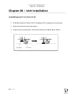
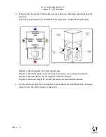
Each side has his specific button color onscreen; here are the player references that are
assigned.
This is very important for any troubleshooting steps (Ref.: Troubleshooting Chapter).
Player 1 is the Red player
; it’s on the drawer side.
Player 2 is the Yellow player
; it’s on the right side when you are facing the drawer.
Player 3 is the Blue player;
it’s the opposite side of the drawer.
Player 4 is the Green player;
it’s on left side wh
en you are facing the drawer.
•
You can install any player box to any positions now as they all have UFO RGB buttons. The player
reference is for the physical setup & configuration.
Содержание Crazy Tower Arcade
Страница 19: ...Crazy Tower Arcade Manual V7 1 Chapter 06 Service Repair 19 P a g e Version GTX 1060 video card ...
Страница 41: ...Crazy Tower Arcade Manual V7 1 Chapter 08 Diagrams Schematics 41 P a g e Power Distribution Schematics ...
Страница 42: ...Crazy Tower Arcade Manual V7 1 Chapter 08 Diagrams Schematics 42 P a g e Players Wiring Current version ...
Страница 43: ...Crazy Tower Arcade Manual V7 1 Chapter 08 Diagrams Schematics 43 P a g e Players Wiring Version 1 Discontinued ...
Страница 46: ...Crazy Tower Arcade Manual V7 1 Chapter 08 Diagrams Schematics 46 P a g e RGB LED Wiring ...


