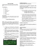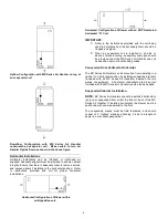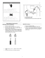
Sequence of Operations
208/240 V, 60 Hz Supply Voltage Models
Cooling
When the thermostat calls for cooling, the circuit between R and G is completed, and the blower relay is energized. The Normally
Open contacts close, causing the indoor blower motor to operate. The circuit between R and Y is also completed; this circuit closes
the contactor in the outdoor fan motor. Circuit R and O or R and B energizes the reversing valve, switching it to the cooling position
(depends on outdoor unit). Air Handler blower turns off 45 seconds after the thermostat stops calling for cooling.
Heating (electric heat only)
When the thermostat calls for heat, the circuit between R and W is completed, and the heater sequencer is energized. A time delay
follows before the heating elements and the indoor blower motor comes on. Units with a second heat sequencer can be connected
with the first sequencer to W on the thermostat sub base or connected to a second stage on the sub base. Air Handler blower turns
off 30 seconds after the thermostat stops calling for heating.
Heating (heat pump with electric heat)
When the thermostat calls for heat, the circuits between R and Y and R and G are completed. Circuit R-Y energizes the contactor
starting the outdoor fan motor and the compressor. Circuit R and G energizes the blower relay starting the indoor blower motor.
Circuit R and O or R and B energizes the reversing valve, switching it to the heating position (depends on outdoor unit).
If the room
temperature should continue to fall, the circuit between R and W1 is completed by the second stage heat room thermostat. Circuit R-
W1 energizes a heat sequencer. The completed circuit will energize supplemental electric heat (if applicable). Units with a second
heater sequencer can be connected with the first sequencer to W1 on the thermostat or connected to a second heating stage W2 on
the thermostat sub base. Air Handler blower turns off 30 seconds after the thermostat stops calling for heating.
Emergency Heat (heat pump with electric heat)
If selector switch on thermostat is set to the emergency heat position, the heat pump will be locked out of the heating circuit, and all
heating will be electric heat (if applicable). A jumper should be placed between W2 and E on the thermostat subbase so that the
electric heat control will transfer to the first stage heat on the thermostat. This will allow the indoor blower to cycle on and off with the
electric heat when the fan switch is in the AUTO position.
Sequence of Operations
Hot Water Heat Models
The Blower Door Safety Switch circuit must be complete for all Sequence of Operations to take place.
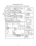
Drawing of Multi-function Control Board, factory installed in all MX Series Air Handlers with hot water heat.
!!Please take precautions while installing the Air Handler to keep Multi-function Control Board and other
controls from getting wet!!
Cooling
When the thermostat calls for cooling, the circuit between R and G is completed. The normally open contacts close, causing the
indoor blower motor to operate. The circuit between R and Y is also completed; this circuit closes the contactor in the outdoor fan
motor. Circuit R and O or R and B energizes the reversing valve, switching it to the cooling position (depends on outdoor unit). The
Air Handler fan will turn off 45 seconds after the Thermostat stops calling for cooling.
17

