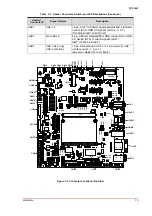
Interfaces
27
Q7-BASE
3.12 USB Signals
3.12.1
Standard USB Interfaces
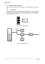
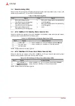
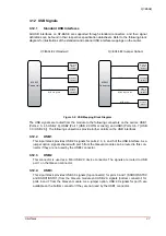
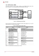
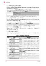
All USB interfaces on Q7-BASE are supported through standard connectors, and their signal
definitions can be found in their respective specification datasheets. Refer to the following block
diagram for illustrations of the standard and optional USB interface mappings on the carrier.
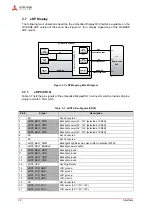
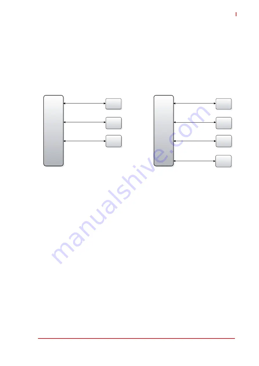
Figure 3-2: USB Mapping Block Diagram
The USB signals are routed from the module to the following connectors on the carrier: USB1
(Ports 2, 3, 4, 5 USB 2.0), USB2 (Port 1 [USB 2.0 OTG or client]), and USB3 (Ports 0, 6, 7 [USB
3.0 / USB 2.0]). The following subsections provide further details on the USB interfaces.
3.12.2
USB1
This 4-port stack provides USB 2.0 signals for ports 2, 3, 4, and 5 of the USB interface. As a
jumper option, signals shared with port 5 from the Qseven module can be routed to this con-
nector if they are not used by the USB3 connector.
3.12.3
USB2
This connector is used as a Mini USB 2.0 device connector. The signals are routed to USB
port 1 on the Qseven connector.
3.12.4
USB3
This 2-port stack provides USB 3.0 signals (top connector) for ports 0 and 1 (SSRX0/SSTX0
and SSRX1/SSTX1) from the Qseven module and USB 2.0 signals (bottom connector) for
ports 6 and 7 from the Qseven module. As a jumper option, USB 2.0 signals for port 5 are
available on the bottom connector if they are not used by the USB1 connector.
Under Development
M iniUSB
(OTG)
(USB2)
4x USB2.0
(USB1)
M XM 2
Connector
USB3.0/
USB2.0
(USB3)
USB ports 2,3,4,5
USB port 1
USB 3.0 ports 0,1
USB 2.0 port 0
Q7-BASE B2 (Standard)
M iniUSB
(OTG)
(USB2)
4x USB2.0
(USB1)
M XM 2
Connector
USB3.0/
USB2.0
(USB3)
USB ports 2,4
USB port 1
USB 3.0 ports 0,1
USB 2.0 ports 0,5
miniPCIe
(CN 74)
USB port 3
Q7-BASE B2 (Jumper Option)