background image

Introduction 

 3 

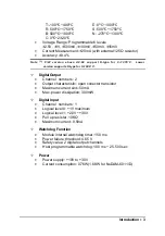
T: -100

°

C~400

°

E: 0

°

C~1000

°

R: 500

°

C~1750

°

S: 500

°

C~1750

°

B: 500

°

C~1800

°

N: -270

°

C~1300

°

C: 0

°

C~2320

°


• 

Voltage Range: Programmable 6 levels  


±

2.5V,  

±

1V,  

±

500mV, 

±

100mV, 

±

50mV, 

±

15mV   

• 

Current Measurement: 

±

20mA (with external 125

 resistor) 

• 

Accuracy:  

±

0.4% 

Note 

(1)

:   F / W   v e r s i o n   a b o v e   A 4 . 6 0   s u p p o r t   K-t y p e   f o r   0 ~ 1 3 7 0

°

C.  Lower 

version supports K-type for 0~1000

°

C. 

² 

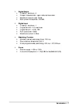
Digital Output 

• 

Channel  numbers: 2  

• 

Output characteristic: open collector transistor 

• 

Maximum current sink: 50mA 

• 

Max. power dissipation: 300mW  


² 

Digital Input 

• 

Channel  numbers: 1  

• 

Logical level 0: +1V maximum  

• 

Logical level 1: +2.0V~ +30V 

• 

Pull up resister: 10K


• 

Maximum current: 0.5mA 


² 

Watchdog Function 

• 

Module internal watchdog timer: 150 ms 

• 

Power failure threshold: 4.65 V 

• 

Safety value: 2 digital output channels 

• 

Host programmable watchdog: 100 ms ~ 25.500 sec 


² 

Power 

• 

Power supply: +10V to +30V 

• 

Current consumption: 0.76W(1.68W for NuDAM-6011/D) 


Содержание NuDAM-6017

Страница 1: ...NuDAM 6011 NuDAM 6014D NuDAM 6012 D NuDAM 6017 NuDAM 6013 NuDAM 6018 Analog Input Modules User s Guide...

Страница 2: ......

Страница 3: ...arising out of the use or inability to use the product or documentation even if advised of the possibility of such damages This document contains proprietary information protected by copyright All ri...

Страница 4: ...O nupro Adlink com tw Software sw Adlink com tw AMB amb Adlink com tw TEL 886 2 82265877 FAX 886 2 82265717 Address 9F No 166 Jian Yi Road Chungho City Taipei 235 Taiwan R O C Please inform or FAX us...

Страница 5: ...RING FOR NUDAM 601X 26 CHAPTER 3 COMMAND SET 32 3 1 COMMAND AND RESPONSE 32 3 2 SUMMARY OF COMMAND SET 34 3 3 SET CONFIGURATION 38 3 4 READ CONFIGURATION 42 3 5 READ MODULE NAME 43 3 6 READ FIRMWARE V...

Страница 6: ...9 3 31 CLEAR LATCHED ALARM 70 3 32 CLEAR EVENT COUNTER 71 3 33 DISABLE ALARM 72 3 34 READ DIGITAL I O AND ALARM STATUS 73 3 35 SET DIGITAL OUTPUT 75 3 36 ENABLE ALARM 76 3 37 SET HIGH ALARM 77 3 38 SE...

Страница 7: ...uDAM 6018 8 channels thermocouple input module V The models with an extended D have the same command set and specification as without D except t he D version has a 5 1 2 LED Display 1 2 Overview of Nu...

Страница 8: ...ital signal or be used as input of the event counter Features of NuDAM 6011 D 1 analog input channel with differential input Programmable voltage range with high gain amplifier On board CJC for temper...

Страница 9: ...type for 0 1000 C Digital Output Channel numbers 2 Output characteristic open collector transistor Maximum current sink 50mA Max power dissipation 300mW Digital Input Channel numbers 1 Logical level 0...

Страница 10: ...setting 7 Y DATA RS 485 series signal positive 8 G DATA RS 485 series signal negative 9 R Vs Power supply 10V 30V 10 B GND Ground 11 TC Thermocouple Input positive Terminal 12 TC Thermocouple Input ne...

Страница 11: ...DATA G DATA R V s B GND High Gain Analog Input 1 10 IN IN D O 1 H I DI0 EV D O 0 L O DEFAULT T C T C Code mV mA Code T C 00 1 5 m V 01 02 03 04 05 06 5 0 m V 100 mV 500 mV 1 V 2 5 V 5 V 0E J Type 0F...

Страница 12: ...s for ND 6012 D 2 digital output channels of open collector type Alarm function with high low alarm output 1 digital input channel event counter Programmable host watchdog timer for host failure prote...

Страница 13: ...300mW Digital Input Channel numbers 1 Logical level 0 1V maximum Logical level 1 2 0V 30V Pull up resister 10K Maximum current 0 5mA Watchdog Function Module internal watchdog timer 150 ms Power fail...

Страница 14: ...or Low alarm output 6 DEFAULT Initial state setting 7 Y DATA RS 485 series signal positive 8 G DATA RS 485 series signal negative 9 R Vs Power supply 10V 30V 10 B GND Ground Functional Block Diagram...

Страница 15: ...Look at ND 6012 D Pin Assignment N D 6 0 1 2 Y DATA G DATA R V s B GND High Gain Analog Input 1 10 IN IN D O 1 H I DI0 EV D O 0 L O DEFAULT Code mV mA 08 09 0A 0B 0C 0D 10V 5 V 1 V 500 mV 100 mV 0 20...

Страница 16: ...wiring Wiring open detection 2 Note 2 for H W version C1 2 or above and F W version C4 6 or above Specifications of NuDAM 6013 Interface Interface RS 485 2 wires Speed bps 1200 2400 4800 9600 19 2K 3...

Страница 17: ...2 12 IEXC2 Current source of CH2 13 SENSE2 Differential negative input of CH2 14 SENSE2 Differential positive input of CH2 15 IEXC2 Current source of CH2 16 AGND1 Analog signal ground of CH1 17 IEXC1...

Страница 18: ...A G N D 10 N D 6 0 1 3 3 CH RTD Input 20 IEXC 1 IEXC 1 AGND 1 IEXC 2 IEXC 2 1 IEXC 0 IEXC 0 AGND 0 V s 0 00385 0 003916 Code Input Range Code Input Range 20 Pt 100 C 100 C 24 Pt 100 C 100 C 21 Pt 0 C...

Страница 19: ...ge 2500 Vrms isolation voltage for AD channel 2 digital output channels of open collector type Alarm function with high low alarm output 1 digital input channel event counter Programmable host watchdo...

Страница 20: ...dissipation 300mW Digital Input Channel numbers 1 Logical level 0 1V maximum Logical level 1 2 0V 30V Pull up resister 10K Maximum current 0 5mA Watchdog Function Module internal watchdog timer 150 ms...

Страница 21: ...Input Positive Terminal 13 15V out External 15V Output 18 DO 0 LO Digital Output Channel 0 or Low alarm output 19 DI 0 EV Digital Input Channel 0 or event counter input 20 DO 1 HI Digital Output Chan...

Страница 22: ...D Pin Assignment DI0 EV DO0 LO VIN VIN IIN IIN DEFAULT Y DATA G DATA B GND 10 N D 6 0 1 4 D Transmitter Input Module 20 DO1 HI 15V out 1 15V out R Vs C o d e m V m A 0 8 0 9 0 A 1 0 V 2 5 V 1 V 0 B 0...

Страница 23: ...rotection Easy programming by software Easy installation and wiring Specifications of NuDAM 6017 Interface Interface RS 485 2 wires Speed bps 1200 2400 4800 9600 19 2K 38 4K 115 2K 115 2K only for fir...

Страница 24: ...hannel 0 12 Vin0 Differential negative input channel 0 13 Vin1 Differential positive input channel 1 14 Vin1 Differential negative input channel 1 15 Vin2 Differential positive input channel 2 16 Vin2...

Страница 25: ...nment N D 6 0 1 7 Y DATA G DATA R V s B GND 8 CH Analog Input 1 10 Vin 5 Vin 5 Vin 6 A G N D Vin 7 DEFAULT Vin 4 Vin 4 Vin 3 Vin 3 Vin 2 Vin 2 Vin 1 Vin 1 Vin 0 Vin 0 11 20 08 09 0A 0B 0C 10V 5 V 1 V...

Страница 26: ...ftware Easy installation and wiring Wiring open detection 5 Specifications of NuDAM 6018 Interface Interface RS 485 2 wires Speed bps 1200 2400 4800 9600 19 2K 38 4K 115 2K 115 2K only for firmware re...

Страница 27: ...ive 8 G DATA RS 485 series signal negative 9 R Vs Power supply 10V 30V 10 B GND Ground 11 Vin0 Differential positive input channel 0 12 Vin0 Differential negative input channel 0 13 Vin1 Differential...

Страница 28: ...A G N D Vin 7 DEFAULT Vin 4 Vin 4 Vin 3 Vin 3 Vin 2 Vin 2 Vin 1 Vin 1 Vin 0 Vin 0 11 20 08 09 0A 0B 0C 10V 5 V 1 V 500 mV 100 mV 0 20 mA CODE mV mA 0D ND 6018 Multiple Analog Input Code mV mA Code T...

Страница 29: ...sful to install the nudism Administration 2 2 Initializing a Brand New Module Objective of Initializing a Brand New NuDAM All NuDAM modules except NuDAM 6520 and NuDAM 6510 in a RS 485 network must ha...

Страница 30: ...le will be possible no matter what configuration is set under operating state Initialization Equipments Host computer with an RS 232 port An installed RS 485 module NuDAM 6520 with 9600 baud rate The...

Страница 31: ...NuDAM modules on the network 3 Power off the NuDAM power supply of the existing RS 485 network 4 Power off the host computer 5 Wire the power lines for the new NuDAM with the existing network Be care...

Страница 32: ...C Single Ended Voltage Input Ground Signal Source S i n g l e E n d e d I n p u t C h a n n e l o f N u D A M 6 0 1 7 6 0 1 8 A G N D I N A D C Current Measurement Current Source R 125 Ohm 1 accuracy...

Страница 33: ...B u f f e r To Micro Processor 5 V G N D DI 0 N u D A M 6 0 1 1 D 6 0 1 2 D D i g i t a l I n p u t C h a n n e l C l o c k S o u r c e Digital Output Connect with Power Loading F r o m M i c r o P r...

Страница 34: ...ization Installation IEXC 1 SENSE SENSE IEXC A GND 2 Wire RTD IEXC 1 SENSE SENSE IEXC A GND IEXC 1 SENSE SENSE IEXC A GND Application RTD Input Wiring for NuDAM 6013 Hardware Reversion A1 3 Wire RTD 4...

Страница 35: ...Initialization Installation 29 Application RTD Input Wiring for NuDAM 6013 Hardware Reversion C3...

Страница 36: ...30 Initialization Installation Application Wiring for NuDAM 6014D Millivolt and Volt Input Process Current Input...

Страница 37: ...Initialization Installation 31 Transmitter wiring for NuDAM 6014D 2 wire Transmitter Input 3 wire Transmitter Input 15V out IN IN...

Страница 38: ...ake with the modules Document Conventions The following syntax conventions describe the NuDAM commands in this manual Leading Code Leading Code is the first characteristic of the NuDAM command All NuD...

Страница 39: ...dingCode 01 Address 2 Command Read Configuration CR Carriage return 0x0D Example 2 checksum is enable User Command 012B7 CR Response 01400600AC CR LeadingCode 01 Address 2 Command Read Configuration B...

Страница 40: ...al commands including set configuration command read configuration reset read module s name or firmware version etc Every NuDAM can response to the general commands The second is the functional comman...

Страница 41: ...rom Channel N Addr ChannelNo 6013 6017 6018 3 22 Read All Analog Data Addr A 6013 6017 6018 3 23 Enable Disable Channel for Multiplexing Addr 5 ChannelVal 6013 6017 6018 3 24 Read Channel Status Addr...

Страница 42: ...ibration Addr 9 Counts 6011 D 6018 3 38 Clear Latch Alarm Addr CA 6011 D 6012 D 6014D 3 39 Clear Event Counter Addr CE 6011 D 6012 D 6014D 3 40 Disable Alarm Addr DA 6011 D 6012 D 6014D 3 41 Read Digi...

Страница 43: ...57 Host is OK ALL 3 58 Note ALL means for ND 6011 D ND 6012 D ND 6013 ND 6014D ND 6017 and ND 6018 1 This function only support on F W version above A4 30 2 These two functions only support between F...

Страница 44: ...s 00 to FF in hexadecimal 2 character NewAddr New address ID if you don t want to change address ID let new address ID equals to the old one 2 character InputRange Define analog input range refers to...

Страница 45: ...t execute any other command during this time period Example User command 0130050600 CR Response 30 CR Item Meaning Description Leading Code Command leading code 01 OldAddr Original address ID is 01 He...

Страница 46: ...T Thermocouple 100 to 400 C 6011 D 6018 11 Type E Thermocouple 0 to 1000 C 6011 D 6018 12 Type R Thermocouple 500 to 1750 C 6011 D 6018 13 Type S Thermocouple 500 to 1750 C 6011 D 6018 14 Type B Therm...

Страница 47: ...code Figure 3 1 Data Format Setting of Analog Input Modules 7 6 5 4 3 2 1 0 Reserved Must to be 0 Checksum 0 disable 1 enable Analog Input Data Format 00 Engineering units 01 of Full Scale Range 10 T...

Страница 48: ...valid Addr Address ID InputRange Current setting of analog voltage input refers to Table 3 1 for details BaudRate Current setting of communication baud rate refers to Table 3 2 for details DataFormat...

Страница 49: ...module name Response Addr ModuleName CR or Addr CR Command is invalid Command is invalid Addr Address ID ModuleName NuDAM module s name could be 6011 6011 D 6012 6012 D 6013 6017 or 6018 4 or 5 chara...

Страница 50: ...and leading code Addr Address ID F Read module firmware version Response Addr FirmRev CR or Addr CR Command is valid Command is invalid Addr Address ID FirmRev NuDAM module s firmware version Example...

Страница 51: ...de 1 character Addr Address ID 2 character RS Software Reset 2 character Response Addr CR or Addr CR Command is valid Command is invalid Addr Address ID Example User command 060RS CR Response 06 CR To...

Страница 52: ...values and stored the values in the module s register at the same time The sampled data can be read by Read Synchronized Data command Syntax CR Command leading code Synchronized sampling command Resp...

Страница 53: ...n sent for the first time since a synchronized sampling command was issued 1 character Data There are four types of Data format refers to Chapter 4 for details Examples User command 064 CR Response 06...

Страница 54: ...InputData CR Delimiter character InputData The input data represents the analog signal The unit of the digits depends on the data format used There are four types of data format The format is set by t...

Страница 55: ...ter Response Addr CR or Addr CR Command is valid Command is invalid Addr Address ID Example User command 060 CR Response 06 CR To perform the span calibration for analog input module address ID is 06H...

Страница 56: ...nnel for Calibration 1 character 0 2 Response Addr CR or Addr CR Command is valid Command is invalid Addr Address ID Example User command 0601 CR Response 06 CR To perform the span calibration for ana...

Страница 57: ...ddr CR Command is valid Command is invalid Addr Address ID Example User command 061 CR Response 06 CR To perform the offset calibration for analog input module at specified address 06 Hex Note To perf...

Страница 58: ...character 0 2 Response Addr CR or Addr CR Command is valid Command is invalid Addr Address ID Example User command 0612 CR Response 06 CR To perform the offset calibration for analog input module ND 6...

Страница 59: ...cter ChannelNo Channel number range 0 7 1 character Range 0 2 For ND 6013 Response InputData CR Delimiter character InputData Input value from a specified channel number the data format is a or sign w...

Страница 60: ...channel Response InputData InputData InputData CR Delimiter character InputData Input value from a specified channel number the data format is a or sign with five decimal digits and a fixed decimal po...

Страница 61: ...bit 3 0 of 1st character control channel 7 4 bit 3 0 of 2nd character control channel 3 0 bit value 0 Disable channel bit value 1 Enable channel 2 character Response Addr CR or Addr CR Command is val...

Страница 62: ...Val CR or Addr CR Command is invalid Command is invalid Addr Address ID ChannelVal bit 3 0 of 1st character controlt channel 7 4 bit 3 0 of 2nd character control channel 3 0 bit value 0 Disable channe...

Страница 63: ...esponse Data CR or Addr CR Command is invalid Data CJC sensor s data Data format is engineering units an or sign with five decimal digits and a decimal fixed point The resolution is 0 1 C Command is i...

Страница 64: ...R Command leading code 1 character Addr Address ID 2 character C Disable enable CJC command 1 character Status 0 Disable 1 Enable Response Addr CR or Addr CR Command is valid Command is invalid Addr A...

Страница 65: ...ding code 1 character Addr Address ID 2 character D Read CJC disable enable staus command 1 character Response Addr Statu s CR or Addr CR Command is valid Command is invalid Stat us 0 Disable 1 Enable...

Страница 66: ...ple detection command code ChannelNo Channel number range 0 7 for specified channel A for all the channel Response Addr OpSts CR or Addr CR Command is invalid Addr Address ID OpSts For specified chann...

Страница 67: ...channel 0 User command 01BA CR Response 1FE CR Command is valid 01 Address ID FE Open thermocouple of channel 1 7 Close thermocouple of channel 0 Notice The open detection function is immediate scanni...

Страница 68: ...e Disable Open thermocouple detection command Status 0 Disable Open thermocouple detection 1 Enable Open thermocouple detection Response Addr CR or Addr CR Command is invalid Addr Address ID Command i...

Страница 69: ...mapping Data format is with an or sign with five decimal digits and a decimal fixed point Data_H High limit value for linear mapping Data format is with an or sign with five decimal digits and a decim...

Страница 70: ...ear mapping Data format is with an or sign with five decimal digits and a decimal fixed point Data_H Mapped high limit value for linear mapping Data format is with an or sign with five decimal digits...

Страница 71: ...format is with an or sign with five decimal digits and a decimal fixed point Data_H High limit input value for linear mapping It must be higher than the low limit input value The format of data is th...

Страница 72: ...Data format is with an or sign with five decimal digits and a decimal fixed point Data_H Mapped high limit input value for linear mapping It must be Higher than mapped the low limit input value Data f...

Страница 73: ...erence to control the linear mapping function Status One char to determine the linear mapping function enable or disable 1 means enable 0 means disable Response Addr CR or Addr CR Command is invalid A...

Страница 74: ...r Address ID R Read to the linear mapping status Response Addr Status CR or Addr CR Command is invalid Addr Address ID Status One char to means the state of linear mapping 1 means enable 0 means disab...

Страница 75: ...libration Counts It is a 4 characters Hexadecimal with a sign or range is 0000 to FFFF each count equals approximately 0 0153 C Example 0042 4x16 2 66 66 0 0153 C 1 009 C Response Addr CR or Addr CR C...

Страница 76: ...at specified analog input module Syntax Addr CA CR Command leading code Addr Address ID CA Clear latched alarm Response Addr CR Command is valid Addr Address ID Example User command 06CA CR Response...

Страница 77: ...input module Syntax Addr CE CR Command leading code Addr Address ID CE Clear event counter Response Addr CR Command is valid Addr Address ID Example User command 06CE CR Response 06 CR Set the event...

Страница 78: ...unctions at specified analog input module Syntax Addr DA CR Command leading code Addr Address ID DA Disable Alarm Response Addr CR Command is valid Addr Address ID Example User command 06DA CR Respons...

Страница 79: ...se Addr Alarm DigitalO DigitalI CR Command is invalid Addr Address ID Alarm 0 alarm is disable 1 MOMENTARY mode enable 2 LATCH mode enable 1 character DigitalO Digital output channel port 0 and 1 stat...

Страница 80: ...le s address ID is 06H 2 Alarm 2 means alarm state is LATCH 03 DigitalO Digital output channel status 03 channel 0 is ON channel 1 is ON 01 DigitalI Digital input channel status 01 digital input is HI...

Страница 81: ...igital output data 2 characters 00 bit 1 is OFF bit 0 is OFF 01 bit 1 is OFF bit 0 is ON 02 bit 1 is ON bit 0 is OFF 03 bit 1 is ON bit 0 is ON Response Addr CR or Addr CR Command is valid Command is...

Страница 82: ...ng code Addr Address ID EA Enable alarm command code Mode M enable alarm to MOMENTARY mode L enable alarm to LATCH mode Response Addr CR Command is valid Addr Address ID Example User command 06EAL CR...

Страница 83: ...s ID HI Set high alarm limit value Data Alarm high limit value Data format is engineering units an or sign with five decimal digits and a decimal fixed point Response Addr CR Command is valid Addr Add...

Страница 84: ...ID LO Set low alarm limit value Data Alarm low limit value Data format is engineering units an or sign with five decimal digits and a decimal fixed point Response Addr CR Command is valid Addr Addres...

Страница 85: ...Address ID RE Read event counter Response Addr Data CR Command is valid Addr Address ID Data 5 character Decimal range 00000 to 65535 if the event counter exceed 65535 then event counter value is 655...

Страница 86: ...limit Response Addr Data CR Command is valid Addr Address ID Data High alarm limit value Data format is engineering units an or sign with five decimal digits and a decimal fixed point Example User com...

Страница 87: ...alarm limit Response Addr Data CR Command is valid Addr Address ID Data Alarm low limit value Data format is engineering units an or sign with five decimal digits and a decimal fixed point Example Use...

Страница 88: ...ddr Address ID Status 2 character Bit 0 Reserved Bit 1 Power failure or watchdog failure Bit 2 Host watchdog is enable Bit 3 Host failure C1 Leading code 1 for read configuration status firmware versi...

Страница 89: ...e command leading code etc default is 1 character C6 Leading code 6 this leading code is reserved default is 1 character Example User command 060 CR Response 0600 CR Command leading code setting is fo...

Страница 90: ...fault is 1 character C2 Leading code 2 for read synchronize sampling digital output default is 1 character C3 Leading code 3 for change configuration default is 1 character C4 Leading code 4 for read...

Страница 91: ...change leading code to A then use A06F to read firmware version of module on address 06 WARNING l We do not recommend users to change the default setting of leading code because it will confuse yourse...

Страница 92: ...ate value Flag 0 Disable host watchdog timer 1 Enable host watchdog timer 1 character TimeOut Host timeout value between this time period host must send Host is OK command to module otherwise module w...

Страница 93: ...d 06211203 CR Response 06 CR 06 Address ID 2 Set host watchdog timer and safe state value 1 Enable host watchdog timer 12 Timeout value 0x12 18 18 100 1800 ms 03 03 00000011 The two digital output cha...

Страница 94: ...ID range 00 FF Flag 0 Host watchdog timer is disable 1 Host watchdog timer is enable 1 character TimeOut Host timeout value Range 01 FF 2 character One unit is 100 ms 01 1 100 100 ms FF 255 100 25 5...

Страница 95: ...otherwise host watchdog timer enable module s output value will go to safety state output value Timeout value and safety state output value is defined in 3 30 Set Host Watchdog Timer Safety Value Synt...

Страница 96: ...ments hexadecimal 4 Ohms Engineering Units Set bit 1 and bit 0 of data format variable to 00 means the data is represented in engineering units This data format including three components 1 sign or 2...

Страница 97: ...Data format and resolution Example 1 Input Range is 5 V Input is 1 37 Volts engineering units 1 3700 CR Example 2 Input Range is 10 V Input is 3 653 Volts engineering units 03 653 CR Example 3 Input R...

Страница 98: ...is 10 V Input is 4 Volts of FSR 040 00 CR 40 100 x 10 V 4 V Example 3 Input Range is Type K thermocouple range 0 C to 1000 C Input is 406 5 C of FSR 040 65 CR 40 65 100 x 1000 C 406 5 C Two s Complem...

Страница 99: ...1000 C Input is 406 5 C Two s complement hexadecimal 3408 CR 406 5 1000 x 32768 13320 2 3408H Ohm Data format bit 1 and 0 set to 11 is ohm presentation This data format including three components 1 s...

Страница 100: ...00 1 A 07 Reserved 08 10V Eng Units 10 000 00 000 10 000 1mV 09 5V Eng Units 5 0000 0 0000 5 0000 100 00 V 0A 1V Eng Units 1 0000 0 0000 1 0000 100 00 V 0B 500mV Eng Units 500 00 000 00 500 00 10 V 0C...

Страница 101: ...Format Full Scale Zero Full Scale Displayed Resolution 00 15mV of FSR 100 00 000 00 100 00 0 01 01 50mV of FSR 100 00 000 00 100 00 0 01 02 100mV of FSR 100 00 000 00 100 00 0 01 03 500mV of FSR 100...

Страница 102: ...s Comp 7FFF 0000 8000 1 LSB 03 500mV 2 s Comp 7FFF 0000 8000 1 LSB 04 1V 2 s Comp 7FFF 0000 8000 1 LSB 05 2 5V 2 s Comp 7FFF 0000 8000 1 LSB 06 20mA 2 s Comp 7FFF 0000 8000 1 LSB 07 Reserved 08 10V 2...

Страница 103: ...Thermocouple Data Format Maximum Minimum Displayed Resolution 0E J 0 C to 760 C of FSR 100 00 000 00 0 01 0F K 0 C to 1000 C of FSR 100 00 000 00 0 01 10 T 100 Cto400 C of FSR 100 00 025 00 0 01 11 E...

Страница 104: ...t range different input range have different apply calibration voltage 2 Apply the correct offset voltage to the analog input module detail voltage value see table 5 1 3 Send Offset Calibration Addr 1...

Страница 105: ...resistance to the analog input module ND 6013 channel 2 detail resistance value see table 5 2 11 Send Offset Calibration Addr 12 to analog input module ND 6013 channel 2 12 Apply the correct span res...

Страница 106: ...till air at constant temperature 2 Place a calibrated temperature meter with a resolution of 0 1 C in close proximity to the CJC sensor of the NuDAM module 3 Send command Read CJC Status Addr 3 to rea...

Страница 107: ...to analog input module five times Actually the address now is 00 so the command is 001 The apply source must be a precision source The error range in 50uV is best CJC Calibration Procedure for Firmwar...

Страница 108: ...nd CJC Offset Calibration Addr 9 Counts to correct the CJC offset error counts is a 4 characters with a sign or range is 0000 to FFFF each count equals approximately 0 0153 C For more detail please re...

Страница 109: ...A 0E J 0 C to 760 C 0 mV 50 mV 0F K 0 C to 1000 C 0 mV 55 mV 10 T 100 C to 400 C 0 mV 30 mV 11 E 0 C to 1000 C 0 mV 78 mV 12 R 500 C to 1750 C 0 mV 25 mV 13 S 500 C to 1750 C 0 mV 19 5 mV 14 B 500 C t...

Страница 110: ...C 00385 200 50 21 Pt 100 0 C to 100 C 00385 200 50 22 Pt 100 0 C to 200 C 00385 200 50 23 Pt 100 0 C to 600 C 00385 350 50 24 Pt 100 100 C to 100 C 003916 200 50 25 Pt 100 0 C to 100 C 003916 200 50 2...

Страница 111: ...ding its specifications or if the serial number has been removed Seller does not assume any liability for consequential damages as a result from our products uses and in any event our liability shall...

Отзывы: