miniBASE-10R
Connectors, Pinouts and Jumpers
27
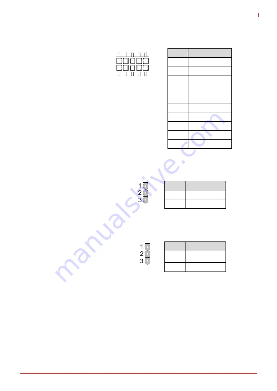
6.14.5. H5: CPLD_JTAG
6.15. Other
Jumpers
6.15.1. JP4: Clear CMOS
To clear CMOS, shut down the power
and short pins 2 and 3
6.15.2. JPX7: BIOS Selection
See 7.1 SPI Secondary BIOS on page 31
for a detailed description.
Note:
<<<< indicates default setting
Pin
Signal
1 CPLD_TCKL
2 GND
3 CPLD_TDO
4 +
3.3V
5 CPLD_TMS
6 N.C.
7 N.C.
8 N.C.
9 CPLD_TDI
10 GND
Pin
Signal
1-2
Normal <<<<
2-3 Clear
CMOS
Pin
Signal
1-2
Module BIOS
<<<<
2-3
Carrier BIOS
Содержание miniBASE-10R
Страница 6: ...vi Preface List of Tables Table 1 miniBASE 10R AB Pin Definitions 14...
Страница 8: ...2 Introduction This page intentionally left blank...
Страница 10: ...4 Features This page intentionally left blank...
Страница 12: ...6 Component Locations This page intentionally left blank...
Страница 14: ...8 Functional Diagram This page intentionally left blank...
Страница 16: ...10 Mechanical Drawing This page intentionally left blank...
Страница 36: ...30 Connectors Pinouts and Jumpers This page intentionally left blank...
Страница 38: ...32 Secondary BIOS This page intentionally left blank...


