List of Figures
vii
List of Figures
Figure 2-1: HSL-4XMO-CG-N/P Mechanical Drawing ................. 8
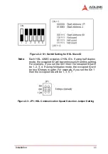
Figure 2-2: S1: Switch Setting for HSL Slave ID........................ 11
Figure 2-3: JP1: HSL Communication Speed Selection Jumper Set-
ting........................................................................... 11
Figure 2-4: P2-3: HSL Full Duplex/Half Duplex Jumper Setting 12
Figure 2-5: JP4: HSL Termination Resistor Jumper Setting ...... 12
Figure 3-1: OUT and DIR Signals on the 4 Axes ....................... 14
Figure 3-2: Non-differential Type Wiring Example ..................... 15
Figure 3-3: EA, EB, and EZ signals ........................................... 16
Figure 3-4: Connection to Line Driver Output ............................ 17
Figure 3-5: Connection to Open Collector Output...................... 18
Figure 3-6: Origin Signal ORG................................................... 18
Figure 3-7: End-Limit Signals PEL and MEL ............................. 19
Figure 3-8: Ramping-down & Position Latch ............................. 20
Figure 3-9: In-position Signal INP .............................................. 20
Figure 3-10: Alarm Signal ALM.................................................... 21
Figure 3-11: Deviation Counter Clear Signal (ERC) .................... 22
Figure 3-12: General-purpose Signal SVON ............................... 22
Figure 3-13: General-purpose Signal RDY .................................. 23
Figure 3-14: Position Compare Output CMP ............................... 23
Figure 3-15: Emergency Stop Input EMG.................................... 24
Figure 3-16: General-purpose Input............................................. 24
Figure 3-17: NPN Type General Purpose Output ........................ 25
Figure 3-18: PNP Type General Purpose Output ........................ 25
Figure 4-1: Communication Block Diagram ............................... 27
Figure 4-2: Single Command Timing ......................................... 29
Figure 4-3: DSP Multi-Tasks...................................................... 30
Figure 4-4: Single Pulse Output Mode (OUT/DIR Mode)........... 32
Figure 4-5: Dual Pulse Output Mode (CW/CCW Mode) ............ 33
Figure 4-6: Velocity Mode Motion .............................................. 34
Figure 4-7: Trapezoidal Motion .................................................. 35
Figure 4-8: Encoder Diagram..................................................... 37
Figure 4-9: S-curve Profile Motion ............................................. 38
Figure 4-10: Automatic Velocity Decrease................................... 39
Figure 4-11: 2 Axes Linear Interpolation...................................... 41
Figure 4-12: 3-Axis Linear Interpolation....................................... 42
Figure 4-13: Circular interpolation for 2 axes............................... 44
Figure 4-14: Circular Interpolation with Acc/dec Time ................. 46
Содержание HSL-4XMO
Страница 4: ......
Страница 16: ...6 Introduction ...
Страница 36: ...26 Signal Connections ...
Страница 61: ...Operation Theory 51 Figure 4 18 home_mode 1 home_mode 3 ORG EZ Slow down Stop Figure 4 19 home_mode 3 ...
Страница 67: ...Operation Theory 57 Home Search Example Home mode 1 Figure 4 29 Home Search Example ...
Страница 108: ...98 Motion Creator in LinkMaster ...


