


12
Getting Started
2.2
LED Indicators
The onboard LED indicators provide board status including error codes and Watchdog and
Ethernet statuses.
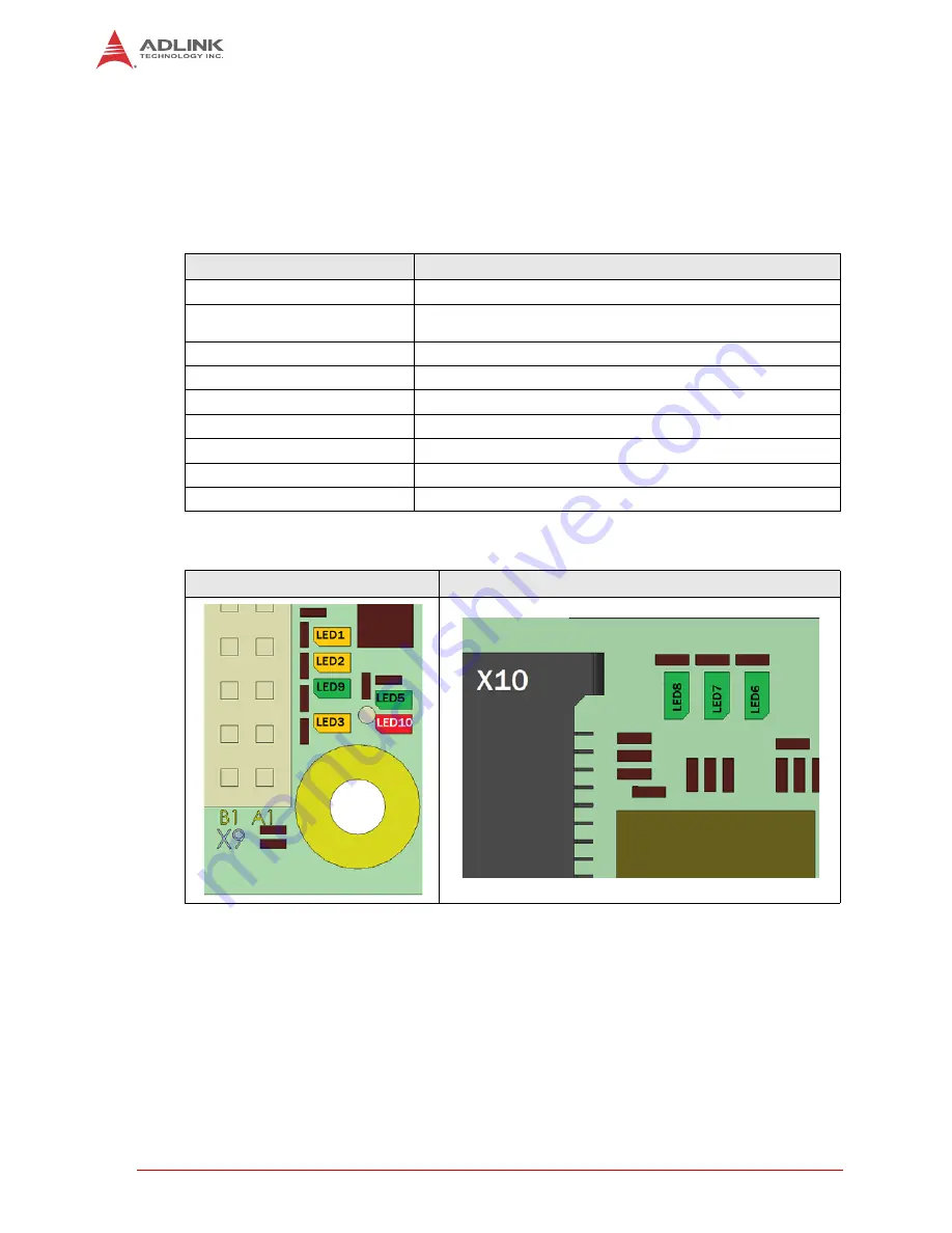
The MiniPCIe LEDs are located on bottom of the board, near the MiniPCIe connector. All other
LEDs are located near the PC/104 connector on the top.
Table 2-2: LED Name and Description
LED
Description
STATUS (LED5, TOP)
Green LED shows error codes in terms of failure.
WD (LED10, TOP)
Red LED lights up when Watchdog was triggered. Can only be
reset by a power off sequence.
ETH0_LINK_ACT (LED3, TOP)
Yellow LED shows link and traffic on Ethernet0 (100 MBit/s)
ETH1_LED_100 (LED9, TOP)
Green LED shows 100MBit link on Ethernet1 (1 GBit/s)
ETH1_LED_1000 (LED1, TOP)
Yellow LED shows 1GBit link on Ethernet1 (1 GBit/s)
ETH1_LED_ACT (LED2, TOP)
Yellow LED shows traffic on Ethernet1 (1 GBit/s)
LED_WWAN (LED6, BOT)
Green LED shows WAN status of MiniPCIe card
LED_WLAN (LED7, BOT)
Green LED shows LAN status of MiniPCIe card
LED_WPAN (LED8, BOT)
Green LED shows PAN status of MiniPCIe card
LED TOP
LED BOTTOM
Содержание CM1-86DX2
Страница 6: ...vi ...
Страница 20: ...14 Getting Started ...
Страница 26: ...20 Module Description LVDS Color Mapping ...
Страница 52: ...46 Using the Module ...
Страница 53: ...Using the Module 47 CM1 86DX2 PCIPnP ...
Страница 54: ...48 Using the Module ...
Страница 56: ...50 Using the Module Chipset screen ...
Страница 57: ...Using the Module 51 CM1 86DX2 ...
Страница 58: ...52 Using the Module ...
Страница 59: ...Using the Module 53 CM1 86DX2 Security screen ...


