ADGT DTU4 0 Series Скачать руководство пользователя страница 21

DTU4x0 GPRS/NB-IoT Data Loggers


User Guide. r. 2.01 | 2022-05-17


Tel.:  +420 234 076 670


21


    e-mail: [email protected]
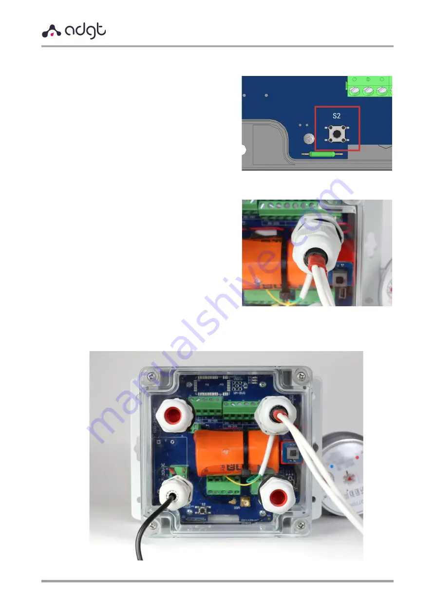
 

8.


Write down initial readings 


Press 

S2

 button to transmit readings to 

the server (when the connection is 
established, indicators 

ST2, ST3

 will start 

flashing).


Remember or write down readings at the 
time of pressing the button. You will need 
this data to enter initial data later in the 
web interface.


9.


Seal the wires and close the DTU cover


a)


Wrap the wires with an insulation tape 
(included) to ensure the necessary 
sealing, and tighten the caps of cable 
glands.


b)


Tightly screw the cover to the base, evenly tightening screw connections. 


Содержание DTU4 0 Series

Страница 1: ...GPRS NB IoT Data Loggers DTU4x0 User Guide Revision 2 01 May 2022...

Страница 2: ...acies Safety Symbols Information The following safety symbols are used in the document Familiarize yourself with the symbols before installing and operating the device WARNING Denotes a hazard It call...

Страница 3: ...switched ON Make sure to power OFF the external power supply before opening the case cover For safety reasons after disconnecting the external power supply wait for 1 second before opening the case c...

Страница 4: ...ption 5 Technical Specifications 6 Appearance 8 DTU4x0 Interfaces and Wiring Diagrams 10 DTU4x0 Operating Modes 13 LED Indication 14 Collection and storage of information 15 Algorithm of data logger c...

Страница 5: ...mote 24 7 access to data via a convenient web interface Power supply both external and autonomous from a backup replaceable 3 6 V battery to provide data logger operation up to 4 years and above The b...

Страница 6: ...rating modes pulse counter high frequency HF pulse counter up to 5kHz two state signal input leakage sensor opening sensor engine hours counter 1 Wire current loop 4 20mA sensor temperature sensor Cou...

Страница 7: ...x mini USB B Antenna Connector DTU4x0 internal flexible antenna 2 5 2dBi on the u Fl connector SMA f connector DTU4x0 F u Fl connector SMA f connector DEFAULT SETTINGS Data slice saving once per hour...

Страница 8: ...r Guide r 2 01 2022 05 17 Tel 420 234 076 670 8 e mail info adgt cz Appearance DTU4x0 is a single board microcontroller device in a sealed plastic IP65 case DTU410 DTU420 7 30 VDC power supply DTU410...

Страница 9: ...ut8 Lower Terminal blocks Terminal block J2 3 pin 7 GND Ground GPIO P1 Universal GPIO 1 P2 Universal GPIO 2 Terminal block J1 2 pin 7 P3 Universal GPIO 3 P4 Universal GPIO 4 Terminal block J14 2 pin 7...

Страница 10: ...nter High frequency pulse counter Signal two state input Leakage sensor ADGT temperature sensor Engine hours sensor DTU case opening sensor 1 Wire Current loop 4 20mA sensor types of devices supported...

Страница 11: ...types of inputs are available for connecting sensors Signal the type of input used when connecting to DTU two state sensors measuring resistance temperature sensors leakage magnetic impact etc Thresh...

Страница 12: ...nt loop sensor the type of input used when connecting 4 20 mA current sensors to data logger When this input is selected a 100 Ohm load resistor is switched on at the input and the 12V and 7 5V power...

Страница 13: ...erver with the subsequent data transfer The default server is https iot24 eu cloud software with access via the web interface Data logger establishes a connection with the server in the following case...

Страница 14: ...re presented in table below Function Condition Description External power connection ST1 is ON External power supply connected ST1 is OFF External power is not connected Switching the device to con fi...

Страница 15: ...ected to a PC SIM operation modes Auto default in this mode DTU registers on SIM card on which the connection was successfully established earlier when first turned on on SIM1 If registration fails da...

Страница 16: ...and its designation should be visually accessible and easily identified by the function performed All installation works should be performed with external and battery power supply disabled Power suppl...

Страница 17: ...ules for crimping stranded wires of meters crimper Installation and Connection 1 Remove data logger case cover by unscrewing four screws on the cover NOTE Inside you will see a battery power jumper in...

Страница 18: ...the two holes in the middle of the board We recommend slightly bending the tip of the cable tie to make it easier to pull it out Place the battery on the top of SIM slots Firmly fix the battery with...

Страница 19: ...able The hole of cable gland A is closed with a rubber plug To insert cables into the plug you need to make an incision of the desired size The holes of cable glands B and C are closed with blind plug...

Страница 20: ...connector Data logger will automatically detect the levels and thresholds at the inputs afterwards will connect to https iot24 eu server and transmit the data to the server To track the beginning and...

Страница 21: ...hed indicators ST2 ST3 will start flashing Remember or write down readings at the time of pressing the button You will need this data to enter initial data later in the web interface 9 Seal the wires...

Страница 22: ...e data logger when connected locally to a PC via USB using the DTU Configuration Tool software You can download the program on our website https adgt cz Firmware Update You can update data logger firm...

Отзывы: