www.addonics.com
Technical Support (M-F 8:30am - 6:00pm PST)
Phone: 408-453-6212
Email: www.addonics.com/support/query/
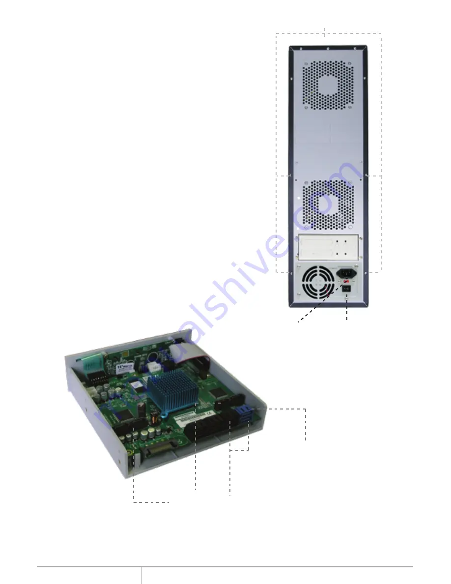
AC input
switch
Main AC switch
Source unit
(top connector)
Target connectors
Removing Cover of Duplicator
NB
Loosen the 3 screws at the back of the tower for
each side panel using a Philips screwdriver.
Push each side panel toward the rear of the
tower to disengage and remove.
Installing drives into the
Duplicator
Each of the 12 remaining bays in the cabinet
can directly secure one 5.25” device such as a
hard drive mounted in a 5.25” bracket or
enclosure. The bays may also be used in
groups to secure larger devices such as a disk
array without the need for modification.
For each of the bays there is one LED located
at the bottom of the cabinet for drive status
indication. There is also one SATA cable for
each drive unit attached to the Duplicator
subsystem. The indicated connector as shown
in the picture connects to the source unit, the
remaining connectors are for target units.
Screws


