background image

20

IN

ST

A

L

L

A

T

IO

N

C

O

N

F

IG

U

R

A

T

IO

N

O

P

ER

A

T

IO

N

FU

R

T

H

ER

IN

F

O

R

M

A

T

IO

N

IN

D

EX

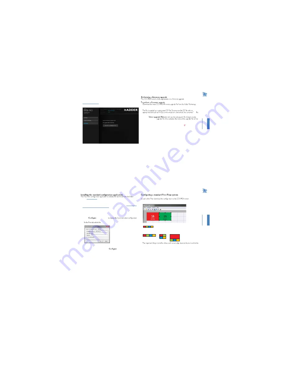
Upgrade

To display the Upgrade page

Note: Firmware upgrades are not possible using the Safari browser, please use a different 
browser when performing upgrades.

Access the CCS Manager

.

2  On the left side, click the 

Upgrade

 button.

website (www.adder.com) and install it on a computer that is attached via a network 
connection to the CCS-PRO4 switch. 


.bin

2  Access the Upgrade page (as detailed left).

3  Click the 

the downloaded 

*.bin

displayed within the Upgrade window.

4  Click the 

Start upgrade

 button. As the process begins, the Upgrade page will show 

‘Upgrade in progress’ and the CCS-PRO4 front panel will show ‘ ’.  

  The upgrade process may take several minutes to complete, after which time the CCS-

PRO4 front panel will return to showing the current channel number.  

21

IN

ST

A

L

L

A

T

IO

N

C

O

N

F

IG

U

R

A

T

IO

N

O

P

ER

A

T

IO

N

FU

R

T

H

ER

IN

F

O

R

M

A

T

IO

N

IN

D

EX

FREE-FLOW CONFIGURATION

website (

www.adder.com

).

1  Install the application onto any computer (not necessarily one of the four computers 

linked to the CCS-PRO4 switch).

2  Connect the computer to the CCS-PRO4 via the network port. See 

To temporarily 

connect a computer to the network port

 for details.

3  Run the installation application and follow the on-screen instructions. Once installed, 

start the Free-Flow application. It may report that it is ‘Unable to communicate with 
the device’. If so:

a  Click the 

OK

 button, whereupon the Free-Flow window will open. 

b  Select 

 > 

Connection...

dialog. 

Network

 connection. The 

Serial

 option is used only for 

the standard CCS4-USB switch.

Use the Free-Flow application to declare the display screens and their positions relative 

1  On the icon bar, click the red, green, blue and yellow screen icons (or use the 

Screens


menu) to add the required number of display screens to the map area:

























  Note: By default, the Free-Flow screen will automatically add four screens in a straight row  

(









), each at a resolution of 1920 x 1080. You can edit or delete these screens 

as required.

2  Arrange the coloured rectangular screen representations to mimic the physical layout 

of the actual displays, for example: 

(Windows PC required)

d  Enter the IP address of the CCS-PRO4 unit (it is set to 192.168.1.22 as standard) as 

well as the username and password, if used. 

e  If required, test the connection. Select 

 > 

Send Layout to Switch

. If 

no error message is returned then you can assume the connection is working.  


CCS-PRO4 switch can determine the correct moments to switch channels. 

  Use the small black squares around the perimeter of each highlighted screen 

representation to change their size or stretch them.


Note:  The numbering of the screen images relate directly to the four channels on the switch.

  continued

Содержание CCS-PRO

Страница 1: ...monitor indicator connections 11 Switching control via the Network port 12 Switching control via the Options port 13 14 Accessing the CCS Manager 14 Status page 15 16 Network settings 17 User accounts...

Страница 2: ...THER INFORMATION INDEX WHAT IS FREE FLOW Adder Free Flow delivers an innovation in K M switching Using Free Flow you can automatically switch between target computers simply by moving the mouse pointe...

Страница 3: ...e OPTIONS port to any network This 10p10c port can separately support the following functions remote control unit see Optional RC4 remote control or a computer with serial port light up monitor indica...

Страница 4: ...PRO4 7 INSTALLATION CONFIGURATION OPERATION FURTHER INFORMATION INDEX Installation LOCATIONS Please consider the following important points when planning the position of the CCS PRO4 switch Situate th...

Страница 5: ...FIGURATION OPERATION FURTHER INFORMATION INDEX Power connections The CCS PRO4 switch is supplied with a single power adapter but offers the facility to use a second input in order to provide operation...

Страница 6: ...the OPTIONS port to any network 11 INSTALLATION CONFIGURATION OPERATION FURTHER INFORMATION INDEX Optional LED monitor indicator connections The optional CCS XB module enables you to add LED Light Emi...

Страница 7: ...for details 13 INSTALLATION CONFIGURATION OPERATION FURTHER INFORMATION INDEX Switching control via the Options port The OPTIONS port allows an external serial input typically from a computer to contr...

Страница 8: ...N OPERATION FURTHER INFORMATION INDEX Status page The Status page provides details about the dual power inputs the internal operating temperature and also allows you to switch peripheral channels To d...

Страница 9: ...all ports even those that are not active or Cycle only active ports This section allows you to optionally apply Name Description and Location details to the CCS PRO4 For larger installations where mul...

Страница 10: ...4 Click the Save button 19 INSTALLATION CONFIGURATION OPERATION FURTHER INFORMATION INDEX Factory reset To display the Factory reset page 1 Access the CCS Manager 2 On the left side click the button 3...

Страница 11: ...instructions Once installed start the Free Flow application It may report that it is Unable to communicate with the device If so a Click the OK button whereupon the Free Flow window will open b Select...

Страница 12: ...has multiple monitors attached 1 agreement you will be prompted to choose a destination folder Either accept the suggested location or change it as necessary Note The Install for all users option sho...

Страница 13: ...all indicators If necessary you can impose default colour and brightness settings upon all connected LED monitor indicators Choose LEDs to display the following popup 4 Choose the CCS XB LED output po...

Страница 14: ...to determine how the various peripherals are switched to one or more computer channels 1 Optional If you need to selectively switch some of your peripherals press the MODE button repeatedly to change...

Страница 15: ...t keys tab or mouse 1 Enter the of the CCS Manager 2 Choose the required Port cycling option either Cycle all ports visits even inactive ports or Cycle only active ports 3 Click the Save button What a...

Страница 16: ...act support form For technical support use the contact form in the Support section of the Further information 31 INSTALLATION CONFIGURATION OPERATION FURTHER INFORMATION INDEX TROUBLESHOOTING Problem...

Страница 17: ...sed is that each computer can be fooled into thinking that the USB device is permanently connected to it even when the device is switched to another computer This means that the enumeration process fo...

Страница 18: ...radio frequency energy emission regulations and ensure a suitably high level of immunity to electromagnetic disturbances European EMC directive 2004 108 EC This equipment has been tested and found to...

Страница 19: ...ted switching 33 Enumerated switching 33 F Front panel switching 27 H Host computer connection 8 Hotkeys selecting computers 28 I Indicators 4 K Keyboard connection 8 M Mouse connection 8 N Network po...

Отзывы: