Overview
LTPH-UG-1166-01
10
July 15, 2002
HMS-317 and HMS-318
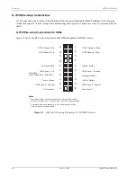
G.703 Wire-wrap Connections
G.703 connections can be made to the individual card connectors through the HMS backplane wire-wrap pins
(0.045-inch square/1.14 mm). Straps for cable dressings and a protective Lexan rear cover are provided with the
shelf.
G.703 Wire-wrap Connections for HDSL
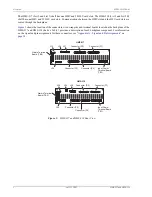
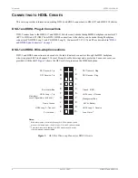
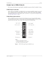
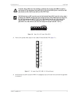
shows the HLU card slot pinouts on the HMS backplane for HDSL circuits.
Figure 10.
HLU Slot Wire-wrap Pinouts for G.703/HDSL Circuits
G.703 Transmit - Tip
G.703
- Ring
Transmit
G.703 Receive - Tip
G.703
Ring
Receive -
A
B
C
D
E
F
J
H
Error Alarm Bus
Ground (GND)
HDSL Loop 1 - Tip
HDSL Loop 1- Receive
Minor Alarm
Loss Of Signal Alarm (LOS ALM) *
Management Bus
Frame Ground
-48 Vdc Battery
HDSL Loop 2 - Transmit
HDSL Loop 2 - Receive
FL (not used)
Fuse Alarm **
1
2
3
4
5
6
7
8
9
10
K
L
**
Fuse alarm is normally floating (0 to -80V maximum) and at -48V
(10 ma maximum) when activated
*
Minor alarm output is normally floating (0 to -60V maximum) and a
ground (10 ma maximum, +5 Vdc for HLU-319 List 2D) when activated
Notes:


