150-204-100-03, Issue 3
Power and Grounding
HRE-204 List 1 and List 2
May 7, 1999
9
T
URN
-
UP
Follow these steps to complete the turn-up procedure:
1
Loosen the 216 HEX security nut on the side panel (
) with a
7
/
16
-inch CAN wrench.
2
Remove the side panel from the chassis to expose the card slots.
3
Insert the card in the assigned slots and refer to the card’s technical practice for the appropriate turn-up
procedure.
If you are using the HRE-204 List 1 and List 2 to locally power one or more HRUs or HLU-431 Line Units,
see
“48 Volt Power Options” on page 9
. If you install an HLU-431 Line Unit into the HRE-204 List 1 and List 2,
see
“HLU Alarm Output Interface” on page 14
for information about the alarm output interface.
P
OWER
AND
G
ROUNDING
The chassis frame and pins 1 and 17 (slot frame ground) of each slot are connected to the HRE-204 List 1 and List
2 ground lug G1, located on the backplane, as shown in
. ADC recommends that the frame
ground lug be connected to earth ground according to the grounding recommendations found in Section 9 of
Bellcore’s GR-1089-DEC, 1996.
48 V
OLT
P
OWER
O
PTIONS
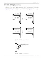
When using the HRE-204 List 1 and List 2 to locally power HRU plugs or HLU-431 line units, the 48 V power
can be provided in either an isolated or non-isolated mode. Power is provided to terminal blocks TB3 and TB4,
the pin assignments for which are shown in
The isolated mode requires two separate external power supplies, which are connected to TB3 for Slots 1 and 2,
and to TB4 for Slots 3 and 4. This isolated mode prevents the loss of all circuits if one power supply fails.
Failure to properly ground the enclosure can cause unsafe voltage levels to occur which can
result in the following adverse situations:
•
a shock hazard to craft personnel who come into contact with the enclosure
•
damage to the installed circuits if the normal discharge path to earth ground of the
enclosure’s secondary surge voltage protection components is missing
•
bit errors due to the inability of the ungrounded enclosure to attenuate the noise inducing
energy from stray EMI fields
•
bit errors due to crosstalk from adjacent communication equipment.
In certain unusual noise environments, it may be necessary to connect the HRU’s circuit ground
pin 17 to frame ground pin 1 of the card-edge connector to remove bit errors from the T1
payload.


