150-454-111-06
Appendix B - Technical Reference
HRE-454
February 25, 2000
57
6
Repeat Step 5 wrapping the pairs on the other side of the field cable stub screen in the same way.
7
Cut the cable stub screen divider approximately 6 inches from the cable stub butt.
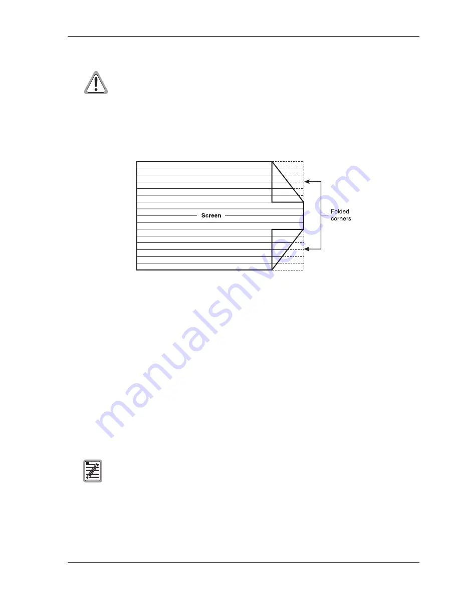
Figure 28.
Screen Folding Diagram
8
Fold each corner at a 45° angle to the center of the screen.
9
Fold the screen divider back on itself several times and tape it to prevent it from unfolding.
10
Position the folded and taped screen divider between the spliced and taped Groups 1 and 2 pairs.
11
Seal and close the splice case according to the splice case instructions.
R
EPLACEMENT
P
ARTS
There are seven replacement or accessory kits that are available for the HRE-454 enclosures.
lists these kits. Following are the topics regarding replacement parts:
•
Replacing the Stainless Steel Dome Cover
•
Replacing LPU Arrestor Boards
The HRE-454 contains replaceable LPU surge arrestors. (See
“Replacing LPU Arrestor Boards” on page 58
instructions on replacing the LPU surge arrestors.) Additionally, ADC recommends that the O-ring be closely
examined whenever the housing is opened for maintenance. Be sure to replace the O-ring if it becomes damaged.
The screen divider is an insulated floating divider that isolates Group 1 (blue thread, side 1 in)
and Group 2 (green thread, side 2 in) from Group 3 (orange thread, side 1 out) and Group 4
(brown thread, side 2 out) in the cable stub.
Do not ground the divider or connect it to the screen divider of the main cable. This may result
in poor performance. The aluminum tape used to wrap the input and output pairs provides the
necessary isolation.
Kits 132-1010, -1011, -1013, -1014; 132-1038-01; and 132-1030-01 are available for damaged
components. Kit 132-1916-01 contains a typical set of nuts and bolts mounting hardware.
Содержание 150-1122-03
Страница 4: ...Inspecting Shipment 150 454 111 06 iv February 25 2000 HRE 454 ...
Страница 45: ...150 454 111 06 Appendix B Technical Reference HRE 454 February 25 2000 37 Figure 18 HRU 512 Pin Assignments ...
Страница 46: ...Appendix B Technical Reference 150 454 111 06 38 February 25 2000 HRE 454 Figure 19 HRU 612 Pin Assignments ...
Страница 49: ...150 454 111 06 Appendix B Technical Reference HRE 454 February 25 2000 41 Figure 22 HRU 402 Pin Assignments ...
Страница 50: ...Appendix B Technical Reference 150 454 111 06 42 February 25 2000 HRE 454 Figure 23 H2TU R 402 Pin Assignments ...
Страница 51: ...150 454 111 06 Appendix B Technical Reference HRE 454 February 25 2000 43 Figure 24 HRE 454 Wiring Interfaces ...
Страница 74: ...Appendix D Glossary 150 454 111 06 66 February 25 2000 HRE 454 ...


