background image

Appendix B - Technical Reference


 150-454-111-06

24

February 25, 2000

 HRE-454

A

PPENDIX

 B - T

ECHNICAL

 R

EFERENCE

Appendix B contains additional technical information about the HRE-454.

CLEI C

ODE


AND

 P1 L

ABELS

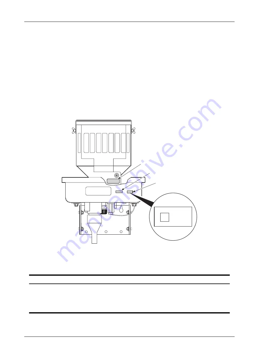
Figure 11

 shows the location on the HRE-454 for the bar code and warranty control number. 

Table 4

 gives a brief 

description of each label.

Figure 11.

HRE-454 Bar Code and P1 Label Locations

Table 4.

HRE-454 Bar Code and P1 Label Information

Number

Components

CLEI/ECI Bar Code Label

Contains human-readable Common Language Equipment Identifier (CLEI) code 
number and Equipment Catalog Item (ECI) bar code number.

P1 Label Date Code

YY = Last two digits of shipment year.
DDD = Julian day

P1 CFG

Xnn = Configuration

Front view

(HRE-454 shown with cover removed)

CLEI/ECI bar code label

P1 label

SERIAL NUMBER

150-1123-01-X

nn

YYDDD

2D

RRRRR

Manufacturer's serial number

Содержание 150-1122-03

Страница 1: ...de HRE 454 1A 150 1122 11 HRE 454 2A 150 1122 21 T1RHM2W4 HRE 454 1B 150 1122 12 T1RHMCV4 HRE 454 2B 150 1122 22 T1RHMCW4 HRE 454 3 150 1122 03 N A HRE 454 4 150 1122 04 N A HRE 454 5 150 1122 05 N A HRE 454 6 150 1122 06 N A HRE 454 Remote Enclosure ...

Страница 2: ...n this document is company private to ADC DSL Systems Inc and shall not be modified used copied reproduced or disclosed in whole or in part without the written consent of ADC Contents herein are current as of the date of publication ADC reserves the right to change the contents without prior notice In no event shall ADC be liable for any damages resulting from loss of data loss of use or loss of p...

Страница 3: ...ts for signs of damage If the equipment has been damaged in transit immediately report the extent of damage to the transportation company and to ADC DSL Systems Inc Order replacement equipment if necessary Check the packing list to ensure complete and accurate shipment of each listed item If the shipment is short or irregular contact ADC DSL Systems Inc as described in Appendix C Product Support o...

Страница 4: ...Inspecting Shipment 150 454 111 06 iv February 25 2000 HRE 454 ...

Страница 5: ...ll Pole or Pedestal Mounting 9 Large Pole or Pedestal Mounting 10 Flat Surface Mounting 11 Rack Mounting 12 Grounding 13 Grounding a Pole Mounted Enclosure 13 Grounding a Flat Surface Mounted Enclosure 15 Slot Chassis Ground Connections 16 Detaching the Dome from the Baseplate 17 Opening the HRE 454 Enclosure 18 Closing the HRE 454 Enclosure 18 Pivoting the Enclosure 19 HiGain Test Card HTC 400 In...

Страница 6: ...icing Procedure 53 Splicing Procedure 55 Post splicing Procedure 56 Replacement Parts 57 Replacing the Stainless Steel Dome Cover 58 Replacing LPU Arrestor Boards 58 Valve Replacement Procedures 60 Pressure Relief Valve 60 Breather Vent Valve 60 Air Stem Valve 61 Pressure Cutoff Valve 61 Appendix C Product Support _________________________________________________________ 63 Appendix D Glossary ___...

Страница 7: ...s 24 12 HRE 454 with Cover Removed 26 13 Lightning Protection Unit LPU 27 14 HRE 454 Vertical And Horizontal Mounting Orientation 32 15 HRE 454 Interface Wiring Diagram and Cable Assignment Drawing 34 16 HRU 412 Pin Assignments 35 17 ERU 412 List 2 Pin Assignments 36 18 HRU 512 Pin Assignments 37 19 HRU 612 Pin Assignments 38 20 HDU 451 HDU 404 and EDU 451 Pin Assignments 39 21 HLU 431 and HLU 432...

Страница 8: ...s and Remote Units 30 6 HRE 454 Deployment Rules for HLU 431 432 Applications vs Type of Doubler Used 31 7 HRE 454 28 pair Cable Stub Wire Pair Assignment for Doubler and Remote Units 33 8 HRE 454 HRU 412 and HRU 402 Wire List 44 9 HRE 454 and ERU 412 List 2 Wire List 46 10 HRE 454 HRU 512 HRU 612 and H2TU R 402 Wire List 47 11 HRE 454 HDU 451 HDU 404 and EDU 451 Wire List 49 12 HRE 454 List 5 and...

Страница 9: ...ure with four single width 400 mechanical slots It has a single gel filled stub List 1A List 1B List 3 and List 5 or air filled stub List 2A List 2B List 4 and List 6 The air filled unit can be pressurized locally or from the main feeder cable through an air core stub This air core stub protects the air filled unit from flooding with water when it is mounted in underground manholes The gel filled ...

Страница 10: ...IEC 950 Electrostatic Discharge ESD compliance and fast transients ENC 5082 1 IEC 801 2 and 801 4 Safety EN 60950 and IEC 950 HRE 454 List 5 and List 6 The HRE 454 List 5 and List 6 are mainly used for housing HLU 431and HLU 432 line units The line units have the same 400 200 mechanics as the doubler and remote units and are used for extending T1 services over distribution pairs that connect fiber...

Страница 11: ...st 2 Figure 17 on page 36 Remote module for 2 pair HDSL E1 2 048 Mbps service G 703 120Ω balanced Table 9 on page 46 HRU 512 Figure 18 on page 37 Remote module for 1 pair HDSL T1 fractional 128 to 786 kbps service Table 10 on page 47 HRU 612 Figure 19 on page 38 Remote module for 1 pair HDSL T1 1 544 Mbps service Table 10 on page 47 HDU 451 HDU 404 and EDU 451 Figure 20 on page 39 Doubler module f...

Страница 12: ...trical balance and permanency The outer jacket provides a flexible protective covering that withstands exposure to sunlight atmospheric temperatures ground chemicals and stresses expected in standard installations The outside diameter of the cable is 0 64 inches 16 25 mm The gel filled unit is similar to the air filled unit Figure 3 on page 6 except that the gel filled unit has a breather vent val...

Страница 13: ...exible protective covering that withstands exposure to sunlight atmospheric temperatures ground chemicals and stresses expected in standard installations The outside diameter of the cable is 0 64 inches 16 25 mm Refer to Table 7 on page 33 for a complete description of the cable stub The HRE 454 cable sealing O ring and V Band seal have been safety tested to 36 pounds per square inch PSI Most cabl...

Страница 14: ...t valve replaces the pressure relief valve if the air filled unit is not pressurized The assembly allows the enclosure to breathe and keeps the internal atmosphere free of harmful contaminants The five metal valves are shown in Figure 4 To avoid pressure buildup the pressure relief valve is set to release air at a maximum pressure of 15 PSI Due to manufacturing tolerances of the springs this maxim...

Страница 15: ...filled unit the pressure cutoff valve in the air filled unit cannot be used to cut off an external air source that is applied to the Schrader air stem valve The air filled unit pressure cutoff valve can only control the air source that is applied to the enclosure through the air core stub ...

Страница 16: ...rm an inventory to verify that all equipment listed on the packing list is present 3 Inspect the enclosure for shipping damage 4 Check the card cage for any sign of breakage 5 Check the O ring for any sign of damage 6 Find and loosen the retaining screws at the rear base of the card cage 7 Tilt the card cage on its hinge 8 Lower the card cage to its level position and tighten the screws to lock it...

Страница 17: ...ure on a pole or pedestal where the pole is less than 7 inches 17 78 cm in diameter The overall enclosure dimensions are shown in Figure 8 on page 17 For details on mounting the pivot bracket refer to Figure 5 Have the following equipment ready before you begin Two 3 8 inch 0 952 cm lug bolts 4 inches 10 16 cm long minimum Table 2 Mounting Details Mounting Page Pole mounting with a pole diameter o...

Страница 18: ...g bracket bolts between 30 and 40 inch pounds 10 If the cable stub connects to an underground cable dress the cable down the pole or pedestal to the splice case If the cable stub connects to an aerial cable form a drip loop in the cable and dress it up the pole or pedestal to the splice case Large Pole or Pedestal Mounting Use the procedure below to mount the enclosure on a pole or pedestal where ...

Страница 19: ...acket Torque the mounting bracket bolts between 30 and 40 inch pounds 11 If the cable stub connects to an underground cable dress the cable stub down the pole or pedestal to the splice case If the cable stub connects to an aerial cable form a drip loop in the stub and dress the stub up the pole or pedestal to the splice case Flat Surface Mounting Use the procedure below to mount the enclosure on a...

Страница 20: ...s between 30 and 40 inch pounds 9 If the cable stub connects to an underground cable dress the cable down the wall to the splice case If the cable stub connects to an aerial cable form a drip loop in the cable and dress it up the wall to the splice case Rack Mounting Use the procedure below when mounting the enclosure in a rack Have the following equipment ready before you begin Four 3 8 inch thru...

Страница 21: ...using bullet bond 2 Drive the ground rod into the ground near the enclosure location The desiccant bags shipped with the unit must be activated prior to closing the lid Do this by removing the bags from their plastic container and placing them inside the enclosure The 8 MIL aluminum shield on the stub is connected to the card cage mounting brackets by a braided shield ground wire shown in Figure 1...

Страница 22: ...nd as a safety measure 8 Using a megger type Ohmmeter measure the main cable shield resistance to ground rods The resistance must be 5 Ω or less 9 If the resistance requirement is not met ground the main cable shield every 2 000 ft Make sure you ground the HRE 454 before splicing the cable stub into the main cable This grounding method or an accepted local grounding method must be in effect at all...

Страница 23: ...ce to ground to comply with the requirement in Step 2 then proceed to Step 4 4 Using 6 AWG cable connect the ground lug on the HRE 454 to the ground connection in the manhole Torque the grounding lug between 18 and 22 inch pounds 5 Using 6 AWG cable connect the main cable shield to the ground connection in the manhole Make sure you ground the HRE 454 before splicing the cable stub into the main ca...

Страница 24: ...nnected to chassis ground This allows them to support 400 200 mechanics plugs which use either pins 1 or 27 for their chassis ground connection If the main feeder cable s shield is bonded to the stub s shield the green insulated or bonded stub shield wire shown in Figure 12 on page 26 should be disconnected from the metal card cage base This is recommended to reduce service affecting noise from be...

Страница 25: ...CHING THE DOME FROM THE BASEPLATE Perform the following steps to detach the dome from the enclosure baseplate Figure 8 1 Release the internal pressure 2 Unclamp the dome from the baseplate 3 Lift the dome up and away from the baseplate Figure 8 HRE 454 Enclosure ...

Страница 26: ...hould break well before the cover clamp is loosened enough to allow the cover to separate from the enclosure Go to step 9 5 Locate the pressure cutoff valve as shown in figure 3 on page 6 Close the pressure cutoff valve by rotating clockwise one 1 full turn blocking the pressure from the main cable 6 Depress the center pin of the air stem to release the remaining pressure within the enclosure 7 Un...

Страница 27: ...tion such as soap and water If you detect a leak tighten the T bolt and tap lightly around the cover clamp Repeat as necessary until the cover is sealed 13 Secure the HRE 454 with a padlock This step is not required for manhole mounted enclosures however a locking assembly is provided PIVOTING THE ENCLOSURE To pivot the enclosure out from its vertical position 1 Loosen the four bolts that connect ...

Страница 28: ...ant to test 2 Set test switch S1 Figure 9 on the card to the type of test you want to perform LOOP BACK LOOP THRU SHORT or OPEN Figure 10 on page 21 illustrates the connection of Tip and Ring pairs of CO and field circuits for each setting of the test switch Pin numbers correspond to edge connector pins for each circuit 3 Perform the selected test Monitor the circuits at the corresponding test poi...

Страница 29: ...tch 1 S1 to select the appropriate test Table 3 Test Connections Test Capabilities LOOP BACK This switch position connects the following circuits CO Tip Pin 7 to CO Tip Pin 41 CO Ring Pin 13 to CO Ring Pin 47 Field Tip Pin 5 to Field Tip Pin 55 Field Ring Pin 15 to Field Ring Pin 49 LOOP THRU This switch position connects the following circuits CO Tip Pin 7 to Field Tip Pin 5 CO Ring Pin 13 to Fie...

Страница 30: ...HTC 400 to be permanently installed in any slot where it provides loop through of the cable pairs This allows end to end metallic cut through access to Sides 1 and 2 cable pairs without the need to rewire the shelf slots CO Ring Pin 47 to Field Ring Pin 49 SHORT This switch position connects the following circuits CO Tip Pin 7 to CO Ring Pin 13 CO Tip Pin 41 to CO Ring Pin 47 Field Tip Pin 5 to Fi...

Страница 31: ... 100 when pressurized Altitude 14 000 ft 4 300 m Mounting 400 mechanics Dimensions Height 21 0 in 53 8 cm Diameter 11 3 in 28 9 cm Depth 14 0 in 35 7 cm Volume 0 75 ft 3 021 m3 Weight HRE 454 List 1A List 3 and List 5 GF 38 lb 17 2 kg a a Shipping weights include stubs and packaging HRE 454 List 2A List 4 and List 6 AF 36 lb 16 3 kg a HRE 454 List 1B GF 51 lb 23 1 kg a HRE 454 List 2B AF 49 lb 22 ...

Страница 32: ...f each label Figure 11 HRE 454 Bar Code and P1 Label Locations Table 4 HRE 454 Bar Code and P1 Label Information Number Components CLEI ECI Bar Code Label Contains human readable Common Language Equipment Identifier CLEI code number and Equipment Catalog Item ECI bar code number P1 Label Date Code YY Last two digits of shipment year DDD Julian day P1 CFG Xnn Configuration Front view HRE 454 shown ...

Страница 33: ...ome and the baseplate There is also a locking cover over the T handle which prevents unauthorized access to the enclosure This cover accepts a padlock with a maximum shackle diameter of 0 3 inch 0 76 cm The V retainer T bolt should be torqued between 10 and 15 inch pounds for proper sealing Card Cage The card cage Figure 12 on page 26 inside the enclosure has four mounting positions which hold up ...

Страница 34: ...ge connector of each slot and provides primary lightning protection for the HDSL loops and customer T1 circuits All HRE 454 units come equipped with four LPUs Each LPU contains four gas tubes which provide the surge protection to each of the four parts These tubes also have three leads which provide protection from Tip and Ring to ground The ground pin is connected to pin 1 of each slot These slot...

Страница 35: ...accompanies the air filled stub The tube connects the inside of the enclosure to the main feeder cable which enables dry air or dry nitrogen to flow from the main cable to the cable stub through the air cutoff valve The air cutoff valve controls the dry air or nitrogen flow through the air inlet tube as described in Air filled Stub Units on page 5 Although the individual gas tubes are field replac...

Страница 36: ...ure conversions 4 Check the threaded hole for debris and clean it if necessary 5 Remove the pressure relief valve from the plastic bag Verify that an O ring is installed on the threaded end of the valve 6 Carefully place the threaded end of the pressure relief valve into the threaded brass fitting from which the breather vent valve was removed 7 Hold the valve straight and push it into the hole Tu...

Страница 37: ...d plugs and in effect causes the heat temperature to significantly rise inside the enclosure The number of doubler or remote units that can be housed in the HRE 454 is dependent upon the Plug type Doubler version the list number of the doubler version will also affect the number of doubler units housed in the HRE 454 Solar exposure Unit orientation Table 5 on page 30 lists the HRE 454 deployment r...

Страница 38: ...l 115 F 46 C 100 F 38 C 125 F 52 C Vertical 4 None 125 F 52 C 110 F 43 C 135 F 57 C Vertical 3 Full 125 F 52 C 110 F 43 C 135 F 57 C Vertical 3 None 135 F 57 C 120 F 49 C 145 F 63 C Vertical 2 Full 135 F 57 C 120 F 49 C 145 F 63 C Vertical 2 None 145 F 63 C 130 F 54 C 155 F 68 C Vertical 1 Full 145 F 63 C 130 F 54 C 155 F 68 C Vertical 1 None 155 F 68 C 140 F 60 C 165 F 74 C Horizontal 4 Full 105 ...

Страница 39: ...07 Max Ambient Temp b b All maximum ambient temperatures of 115 F 46 C or more comply with the outside deployment requirements of Section 10 2 1 3 in TA NWT 001210 HDU 439 437 List 1 and List 1B HDU 431 List 3 List 3B List 4 and List 4B Max Ambient Temp b Vertical 4 Full 115 F 46 C 105 F 40 C Vertical 4 None 125 F 52 C 115 F 46 C Vertical 3 Full 125 F 52 C 115 F 46 C Vertical 3 None 135 F 57 C 125...

Страница 40: ... span to the remote unit is also 35 dB 2 If the first rule is not applicable then make all the spans the same electrical length same 196 kHz loss This minimizes span loss and maximizes operating margin which will result in optimum transmission performances If specific application constraints preclude using Rule 2 or two different circuit layout choices have the same maximum span loss then use Rule...

Страница 41: ... T1 terminology which describes a unidirectional simplex service HDSL is in fact a bidirectional duplex Table 7 HRE 454 28 pair Cable Stub Wire Pair Assignment for Doubler and Remote Units HRE 454 Slot No Direction Side Group a a Group 1 Blue Thread Group 2 Orange Thread Color Tip Color Ring Pair Number 1 In 1 1 White Blue 1 2 In 1 1 White Orange 2 3 In 1 1 White Green 3 4 In 1 1 White Brown 4 1 I...

Страница 42: ...ications The four spare pairs used to access the HLU 431 system relay alarm controls are also shown The wiring from the cable stub entry to the card cage connectors and to the order wire connector is factory installed The wiring diagram Figure 15 is located on the inside of the stainless steel dome for easy reference Figure 15 HRE 454 Interface Wiring Diagram and Cable Assignment Drawing Each powe...

Страница 43: ...e inserted Insert the units into the desired shelf slot by lining up the gold fingers on each unit with the slot connector Active pins are highlighted in black The HTC 400 test card can be inserted into a slot to make a through connection see Test Capabilities on page 21 for more information Figure 16 HRU 412 Pin Assignments This HRE 454 is not compatible with T1 repeaters ...

Страница 44: ...Appendix B Technical Reference 150 454 111 06 36 February 25 2000 HRE 454 Figure 17 ERU 412 List 2 Pin Assignments ...

Страница 45: ...150 454 111 06 Appendix B Technical Reference HRE 454 February 25 2000 37 Figure 18 HRU 512 Pin Assignments ...

Страница 46: ...Appendix B Technical Reference 150 454 111 06 38 February 25 2000 HRE 454 Figure 19 HRU 612 Pin Assignments ...

Страница 47: ...150 454 111 06 Appendix B Technical Reference HRE 454 February 25 2000 39 Figure 20 HDU 451 HDU 404 and EDU 451 Pin Assignments ...

Страница 48: ...Appendix B Technical Reference 150 454 111 06 40 February 25 2000 HRE 454 Figure 21 HLU 431 and HLU 432 Pin Assignments Supported by HRE 454 List 5 and List 6 ...

Страница 49: ...150 454 111 06 Appendix B Technical Reference HRE 454 February 25 2000 41 Figure 22 HRU 402 Pin Assignments ...

Страница 50: ...Appendix B Technical Reference 150 454 111 06 42 February 25 2000 HRE 454 Figure 23 H2TU R 402 Pin Assignments ...

Страница 51: ...150 454 111 06 Appendix B Technical Reference HRE 454 February 25 2000 43 Figure 24 HRE 454 Wiring Interfaces ...

Страница 52: ...ust be fused at 1 5 amps Table 8 HRE 454 HRU 412 and HRU 402 Wire List HRE 454 Slot No Signal Side Group a Color Connector Pair 1 HDSL 1 Tip 1 1 White J1 Pin 7 1 1 HDSL 1 Ring 1 1 Blue J1 Pin 13 1 HDSL 2 Tip 2 2 White J1 Pin 41 5 1 HDSL 2 Ring 2 2 Slate J1 Pin 47 1 DS1 TX Tip 2 1 White J1 Pin 55 5 1 DS1 TX Ring 2 1 Slate J1 Pin 49 1 DS1 RX Tip 1 2 White J1 Pin 5 1 1 DS1 RX Ring 1 2 Blue J1 Pin 15 ...

Страница 53: ...Green J4 Pin 47 4 DS1 TX Tip 2 1 Red J4 Pin 55 8 4 DS1 TX Ring 2 1 Green J4 Pin 49 4 DS1 RX Tip 1 2 White J4 Pin 5 4 4 DS1 RX Ring 1 2 Brown J4 Pin 15 Order wire Tip 1 Red Order Wire Term 9 Order wire Ring 1 Brown Order Wire Term Spare Tip b 2 Red 9 Spare Ring b 2 Brown Spare Tip 2 Red 10 Spare Ring 2 Slate Spare Tip b 1 Red 10 Spare Ring b 1 Slate Spare 2 Black 11 Spare 2 Blue Spare b 1 Black 11 ...

Страница 54: ... G 703 120Ω RX Tip 1 2 White J2 Pin 5 2 2 G 703 120Ω RX Ring 1 2 Orange J2 Pin 15 3 HDSL 1 Tip 1 1 White J3 Pin 7 3 3 HDSL 1 Ring 1 1 Green J3 Pin 13 3 HDSL 2 Tip 2 2 Red J3 Pin 41 7 3 HDSL 2 Ring 2 2 Orange J3 Pin 47 3 G 703 120Ω TX Tip 2 1 Red J3 Pin 55 7 3 G 703 120Ω TX Ring 2 1 Orange J3 Pin 49 3 G 703 120Ω RX Tip 1 2 White J3 Pin 5 3 3 G 703 120Ω RX Ring 1 2 Green J3 Pin 15 4 HDSL 1 Tip 1 1 W...

Страница 55: ...re List HRE 454 Slot No Signal Side Group Color Connector Pair 1 HDSL2 Tip 1 1 White J1 Pin 7 1 1 HDSL2 Ring 1 1 Blue J1 Pin 13 1 Not Used 2 2 White J1 Pin 41 5 1 Not Used 2 2 Slate J1 Pin 47 1 DS1 TX Tip 2 1 White J1 Pin 55 5 1 DS1 TX Ring 2 1 Slate J1 Pin 49 1 DS1 RX Tip 1 2 White J1 Pin 5 1 1 DS1 RX Ring 1 2 Blue J1 Pin 15 2 HDSL 2 Tip 1 1 White J2 Pin 7 2 2 HDSL 2 Ring 1 1 Orange J2 Pin 13 2 N...

Страница 56: ...Pin 55 8 4 DS1 TX Ring 2 1 Green J4 Pin 49 4 DS1 RX Tip 1 2 White J4 Pin 5 4 4 DS1 RX Ring 1 2 Brown J4 Pin 15 Order wire Tip 2 1 Red Order Wire Term 9 Order wire Ring 2 1 Brown Order Wire Term Spare Tip 2 Red 9 Spare Ring 2 Brown Spare Tip 2 Red 10 Spare Ring 2 Slate Spare Tip 1 Red 10 Spare Ring 1 Slate Spare 2 Black 11 Spare 2 Blue Spare 1 Black 11 Spare 1 Blue Spare 2 Black 12 Spare 2 Orange S...

Страница 57: ...2 HDSL 2 Out Ring 2 1 Blue J2 Pin 49 2 HDSL 1 Out Tip 1 2 White J2 Pin 5 2 2 HDSL 1 Out Ring 1 2 Orange J2 Pin 15 3 HDSL 1 in Tip 1 1 White J3 Pin 7 3 3 HDSL 1 In Ring 1 1 Green J3 Pin 13 3 HDSL 2 In Tip 2 2 Red J3 Pin 41 7 3 HDSL 2 In Ring 2 2 Orange J3 Pin 47 3 HDSL 2 Out Tip 2 1 Red J3 Pin 55 7 3 HDSL 2 Out Ring 2 1 Orange J3 Pin 49 3 HDSL 1 Out Tip 1 2 White J3 Pin 5 3 3 HDSL 1 Out Ring 1 2 Gr...

Страница 58: ...e 2 Black 12 Spare 2 Orange Spare 1 Black 12 Spare 1 Orange Spare 2 White SP1 Spare 2 Red Spare 1 White SP1 Spare 1 Red Spare 2 White SP2 Spare 2 Black Spare 1 White SP2 Spare 1 Black Group 1 Blue Thread Group 2 Orange Thread Table 11 HRE 454 HDU 451 HDU 404 and EDU 451 Wire List Cont HRE 454 Slot No Signal Side Group Color Connector Pair ...

Страница 59: ...2 2 Blue J2 Pin 47 2 DS1 TX Tip 2 1 Red J2 Pin 55 6 2 DS1 TX Ring 2 1 Blue J2 Pin 49 2 DS1 RX Tip 1 2 White J2 Pin 5 2 2 DS1 RX Ring 1 2 Orange J2 Pin 15 3 HDSL 1 Tip 1 1 White J3 Pin 7 3 3 HDSL 1 Ring 1 1 Green J3 Pin 13 3 HDSL 2 Tip 2 2 Red J3 Pin 41 7 3 HDSL 2 Ring 2 2 Orange J3 Pin 47 3 DS1 TX Tip 2 1 Red J3 Pin 55 7 3 DS1 TX Ring 2 1 Orange J3 Pin 49 3 DS1 RX Tip 1 2 White J3 Pin 5 3 3 DS1 RX...

Страница 60: ...rm Relay Normally open 1 Black J1 Pin 30 12 1 System Alarm Relay Wiper 1 Orange J1 Pin 22 3 48 Vdc 2 White J3 Pin 17 48 Vdc Power GND 4 48 Vdc 2 White J4 Pin 17 3 48 Vdc 2 Red J3 Pin 35 48Vdc Power 4 48 Vdc 2 Red J4 Pin 35 1 48 Vdc 1 White J1 Pin 17 48 Vdc Power GND 2 48 Vdc 1 White J2 Pin 17 1 48 Vdc 1 Red J1 Pin 35 48Vdc Power 2 48 Vdc 1 Red J2 Pin 35 Spare 2 White SP2 Spare 2 Black Spare 1 Whit...

Страница 61: ...cable pair integrity when splicing stub pairs into the main cable The T1 lines must have correct cable pair connection However the HDSL units will compensate if cable pairs are reversed but may give false indications when trouble occurs Follow normal procedures as required Pre splicing Procedure Perform the following to pre splice the enclosure cable stub 1 Strip a sufficient length of the outer j...

Страница 62: ...paper towel 7 Keep cable pairs dry Cover the exposed splice to protect it from the elements if it is left unattended prior to completion Figure 26 Dress Splice in Splice Case When the air temperature is low warm the cable pairs to aid in removing grease by cleaning the stub in a heated enclosure or by using a heat gun to apply warm air to the pairs Avoid applying excessive heat which could deform ...

Страница 63: ...cable to the CO side of the cable stub with a straight splice 4 Once the cables are connected wrap the CO splice with aluminum tape or dress out the splice according to local procedures 5 Connect the field side of the cable stub to the field side of the main cable with a straight splice 6 Once the cables are connected wrap the field splice with aluminum tape as shown in or dress out the splice acc...

Страница 64: ...s on one side of the screen with 2 inch pressure sensitive aluminum tape Overlay the tape by one half its width and form the tape in place Aluminum tape provides electrical isolation from outside EMI sources For these applications dress out the splice per local practices 4 Repeat Step 3 wrapping the pairs on the other side of the screen in the same way 5 Starting at the cable stub butt of the fiel...

Страница 65: ...g replacement parts Replacing the Stainless Steel Dome Cover Replacing LPU Arrestor Boards The HRE 454 contains replaceable LPU surge arrestors See Replacing LPU Arrestor Boards on page 58 for instructions on replacing the LPU surge arrestors Additionally ADC recommends that the O ring be closely examined whenever the housing is opened for maintenance Be sure to replace the O ring if it becomes da...

Страница 66: ...clamp of dust and debris 2 Remove the clamp and dome cover as described in Replacement Parts on page 57 3 Remove the defective LPU board 4 Insert a new LPU board in the vacant position 5 Replace other defective LPU boards in the same manner Note that the LPU board must be reattached so that pin 1 of the board is connected to the edge connector pin which in turn is connected to the green or braided...

Страница 67: ...r Qty 1 Security Cover 132 1014 01 V Band and Accessories Qty 1 O Ring Qty 1 V Band Metal Locking Clamp Qty 1 Bag Desiccant 2 units 132 1038 01 Valve Kit Metal Qty 2 Breather Vent Valves BVV Qty 2 Pressure Relief Valves PRV Qty 2 Air Stem Valve and Caps ASV Qty 2 Pressure Cutoff Valves PCV Qty 2 Air Intake T Valve Caps Qty 2 Bag Desiccant 2 units 132 1016 01 Installation Hardware Qty 4 3 8 16 x 1 ...

Страница 68: ...RV by turning it counterclockwise then remove it by hand If the adapter nut becomes loose tighten it to a torque of 60 inch pounds 3 Check that the O ring in the adapter s inner well has remained in place If not reseat it 4 Thread the new PRV into the adapter Do not crossthread 5 Again grip the adapter nut with a 3 4 inch wrench and the PRV with a 1 2 inch wrench Tighten the PRV to 120 inch pounds...

Страница 69: ...t of an all metal nickel plated assembly as shown in Figure 4 on page 7 The valve controls the flow of air from the air core stub air filled unit or the external air inlet valve gel filled unit into the enclosure The assembly consists of an adjusting knob with stem that is inner locked to a limiting nut The outer limiting nut screws into the outer threads of the body housing connected to the enclo...

Страница 70: ... clockwise until contact is felt between the stem s O rings and the inner threads of the body housing 10 Use the 1 inch wrench to torque the limiting nut to 200 inch pounds 11 Check that the adjusting knob has at least one and one half turns of free movement in and out 12 If any binding occurs loosen the limiting nut and turn the adjustment knob until it moves freely Retighten the limiting nut 13 ...

Страница 71: ...Turn Up and Testing Network Monitoring upstream or downstream Power Monitoring and Remote Surveillance Service Maintenance Agreements Systems Operation ADC Technical Assistance Center 800 638 0031 714 730 3222 Fax 714 730 2400 Email wsd_support adc com Technical Information System Network Configuration Product Specification and Application Training product specific Installation and Operation Assis...

Страница 72: ...lve CLEI Common Language Equipment Identified cm Centimeter CO Central Office dB Decibel DDS Digital Data System ECI Equipment Catalog Item EMI Electromagnetic Interference HDSL High bit rate Digital Subscriber Line HDU HiGain Doubler Unit HLU HiGain Line Unit HRE HiGain Remote Enclosure HTC HiGain Test Card ICEA Insulated Cable Engineers Association IS Inner Statial ISDN Integrated Services Digit...

Страница 73: ...ry HRE 454 February 25 2000 65 Ohms Measures of resistance PCV Pressure Cutoff Valve PE Processing Element PRV Pressure Relief Valve PSI Pounds per Square Inch REA Rural Electrification Administration RMA Return Material Authorization ...

Страница 74: ...Appendix D Glossary 150 454 111 06 66 February 25 2000 HRE 454 ...

Страница 75: ...30 days from the date of purchase the media on which software is stored will be free from material defects under normal use ADC will replace defective media at no charge if it is returned to ADC during the 30 day warranty period along with proof of the date of shipment The transportation charges for shipment of returned products to ADC will be prepaid by the Buyer ADC will pay transportation charg...

Страница 76: ...ED FIRM ISO 9001 TL 9000 ADC DSL Systems Inc 14402 Franklin Avenue Tustin CA 92780 7013 Tel 714 832 9922 Fax 714 832 9924 Technical Assistance Tel 800 638 0031 Tel 714 730 3222 Fax 714 730 2400 DOCUMENT 150 454 111 06 JC 0a 1242350 ...

Отзывы: