3.2 Connection to the Ethernet Network
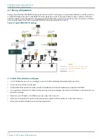
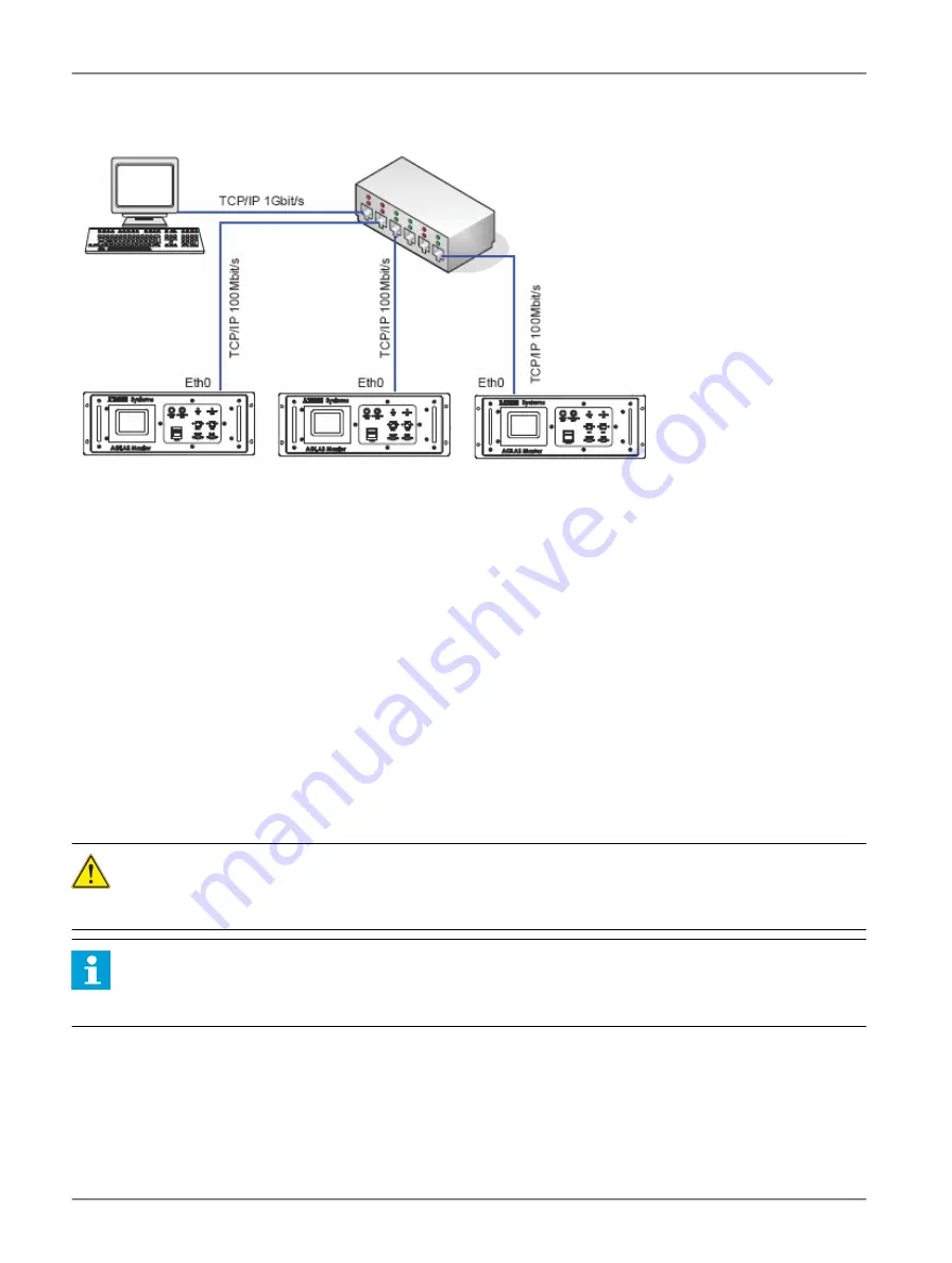
Figure 8: Ethernet connections
RELIANCE IL Master 1
RELIANCE IL Master 2
RELIANCE IL Master 3
RELIANCE IL PC
TCP/IP Network
switch with
IEEE1588 PTP
The RELIANCE IL Master is to be connected via a shielded CAT5 network cable, with RJ45 plugs to the ETH-0 port and the hub
or switch of the Ethernet network. The cable is to be run as a 1:1 connection or Eth-1.
The usual segment length restrictions for Ethernet networks apply.
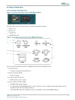
For the location of the Ethernet connectors: refer to
.
3.3 Earth Grounding
To protect the devices against surges that could be caused by a lightning strike, each RELIANCE IL Master is to be earth
ground separately via the earth ground screw, with minimum induction or resistance. For this an earth ground cable with a
suitable cable lug is to be fixed to the earth ground screw on the RELIANCE IL Master (M6 screw thread). The cross-sectional
area of the cable should be at least AWG 8 (6mm2) with a maximum cable length of 39” (1m).
All masters ground terminals must be connected to a common earth grounded bar in the vault or substation.
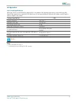
For the location of the earth ground screw: refer to
3.4 Safety Instructions
DANGER
Work on the incoming power supply systems or the series circuit must only be carried out by trained, qualified staff.
Follow the currently applicable regulations according to local and international standards.
Note
The RELIANCE IL Master is maintenance free.
The RELIANCE IL Master may only be opened by authorized maintenance personnel.
RELIANCE Intelligent Lighting Platform II
Installation of stand-alone RELIANCE IL Masters
20
Copyright
©
ADB Safegate, All Rights Reserved


