


R
EPLACING
THE
B
ILLBOARD
R
OUTER
M
AY
6, 2008
3
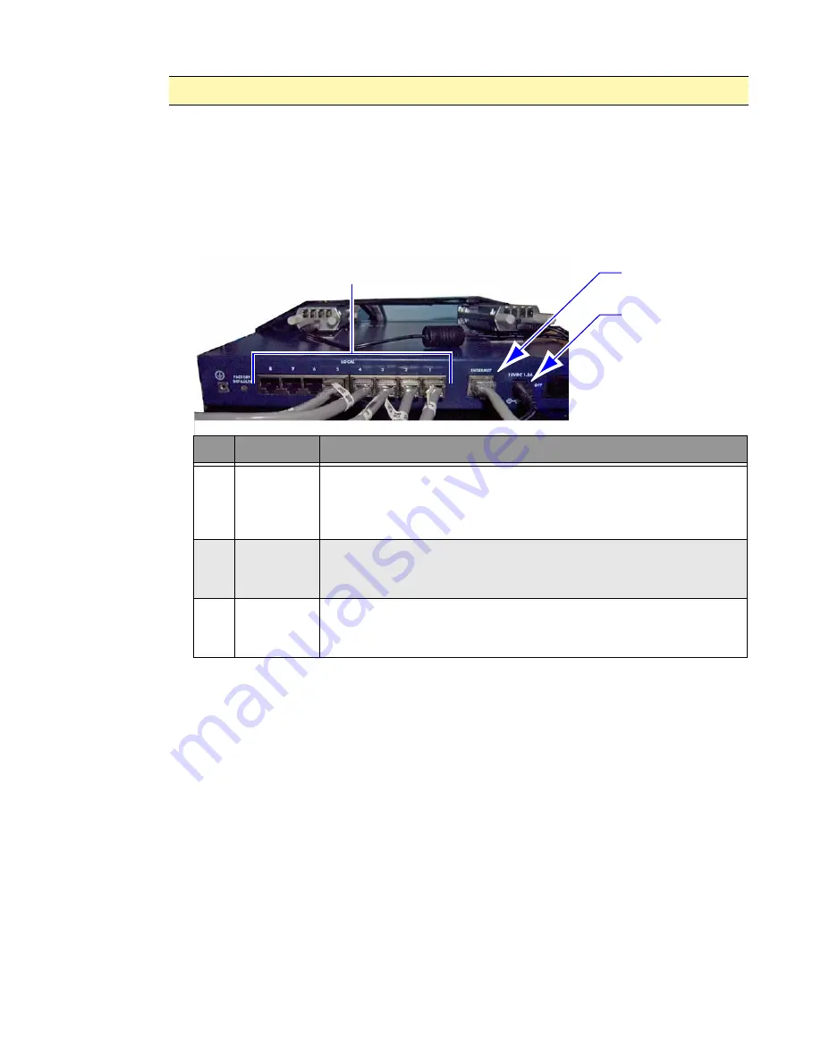
6. Connect the Ethernet cables and power cord to the router, see Figure 3.
•
Route the power adapter cord along the same pathway as the previous cord.
Connect the power adapter to the UPS and the router.
•
Using the tie wraps, secure the power adapter cord near the same locations as
the previous cord.
•
Connect the ISP Internet cable to the router’s Internet port.
•
Connect the Ethernet cables to the router’s local ports.
Figure 3. Router cable connections.
7. Turn on the router.
8. If applicable, change the IP address on the router. This step is required only if the IP
address was not supplied to Adaptive at the time of the order. See “Changing the
router’s settings” on page 4 for procedure details.
Verifying router operation
The router is operating properly if the following can be performed from a remote Internet
connection:
Change or update the message content on the Billboard.
Access the UPS’s web console.
If applicable, access the camera and view the face of the Billboard.
Notice:
Do not over tighten the tie wraps. Otherwise damage to cord may occur.
A
B
C
Item
Name
Description
A
LOCAL
PORTS 1-8
The control cabinet’s PC controllers, UPS’s SNMP / Web card, and the
optional diagnostic camera’s PoE (Power over Ethernet) device all
connect to the router’s eight 10/100 Mbps ports. These component
cables may plug into any of the local ports.
B
INTERNET
PORT
Only plug the ISP’s cable into the router’s Internet port.
This
connection supplies Internet access to all the cabinet components
connected to the local ports.
C
POWER
ADAPTER
PORT
The power adapter plugs into receptacle #6 (bottom–left receptacle in
load #3) on the UPS. 12VDC 1.2A power is supplied to the router via
the power adapter cord.


