Adaptive NETGEAR 1109503001SP Скачать руководство пользователя страница 2

R

EPLACING


THE

 B

ILLBOARD

 R

OUTER

2

PN 1109610109 

REV

. B

Replacing the router

To replace the router

Billboard operation will continue during this procedure but the content on the 
billboard cannot be changed or updated until this procedure is completed.

Do not disconnect power from the billboard or the control cabinet.

1.  Open the control cabinet’s front door. When facing the front of the cabinet the load 

center will be on the right.

If applicable, remove the control cabinet’s padlock.

Turn cabinet handle and pull open the cabinet door.

2.  Turn off the router. The router is located on the top shelf inside the cabinet.

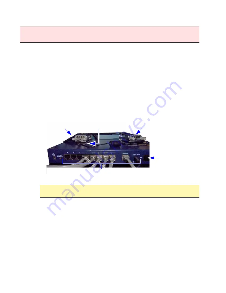
3.  Unplug the Ethernet cables from the router.

Note: 

Single billboard configurations will have less cables plugged into the router’s 
local ports and only one DVI / Fiber converter attached to the top.

Figure 2. Rear view of a dual billboard router configuration.

4.  Remove the router and power adapter from the control cabinet. 

Loosen the velcro strap around the router.

Detach the DVI / Fiber converter(s) from the top of the router.

Remove all tie wraps from the power adapter cord’s pathway to the UPS.

Remove the defective router and power adapter.

5.  Position and secure the replacement router.

Attach the appropriate sticky back velcro piece to the top of the router.

Place the router in the same position on the shelf as the previous router. The back 
of the router faces the front of the cabinet.

Attach the DVI / Fiber converters to the velcro on top of the router.

Using the velcro strap, secure the router assembly to the shelf.

WARNING! 

Possible fall hazard. When servicing billboard components, service personnel must use 

a full body safety harness with lanyard. Connect the lanyard to the billboard head’s safety cables; 
otherwise serious injury or death may occur.

Velcro strap

DVI / Fiber converter

Disconnect cables

On / Off switch

Sticky back velcro

Notice: 

Do not crimp, kink, or disconnect the fiber optic cabling connected to the

DVI / Fiber converter. Otherwise billboard will not function properly.

Содержание NETGEAR 1109503001SP

Страница 1: ...net The router splits the incoming Internet signal from the Internet Service Provider s ISP hardware device into eight 10 100 Mbps local ports The control cabinet s PC controllers UPS s SNMP Web card and the optional diagnostic camera s PoE Power over Ethernet device all connect to the router Figure 1 Front view of billboard router Before you begin Kit contents Not all components are required to b...

Страница 2: ...er adapter from the control cabinet Loosen the velcro strap around the router Detach the DVI Fiber converter s from the top of the router Remove all tie wraps from the power adapter cord s pathway to the UPS Remove the defective router and power adapter 5 Position and secure the replacement router Attach the appropriate sticky back velcro piece to the top of the router Place the router in the same...

Страница 3: ... router is operating properly if the following can be performed from a remote Internet connection Change or update the message content on the Billboard Access the UPS s web console If applicable access the camera and view the face of the Billboard Notice Do not over tighten the tie wraps Otherwise damage to cord may occur A B C Item Name Description A LOCAL PORTS 1 8 The control cabinet s PC contr...

Страница 4: ...rawer 2 Pull the front handle and slide the KVM drawer out until it stops 3 Lift handle up to open the KVM drawer 4 Press the power on button A 5 Press the 7 selection button B to access PC Controller 1 s desktop Figure 4 Key components of KVM drawer 6 Type http 192 168 0 100 in a web browser s address bar and press Enter 7 At the login prompt type admin for the login and password Figure 5 Router ...

Страница 5: ...asic Settings as shown in the following diagram Figure 7 Router basic settings Click Basic Settings Select No Select Use Static IP Address Enter IP Address Provided by your Internet Service Provider Enter IP Subnet Mask Enter Gateway IP Address Select Use These DNS Servers Enter Primary DNS address Click Apply to save your settings ...

Страница 6: ...REV B 10 Click OK to restart the router Figure 8 Router restart prompt 11 After the router restarts click Logout Figure 9 Router logout 12 Click Yes to exit Figure 10 Router exit prompt 13 Verify router operation see page 3 for details Click Logout ...

Отзывы: