background image

© Copyright 2008 Adaptive Micro Systems LLC. All rights reserved.

Adaptive Micro Systems • 7840 North 86th Street • Milwaukee, WI 53224 USA • 414-357-2020 • 414-357-2029 (fax) • http://www.adaptivedisplays.com

Adaptive is a registered trademark of Adaptive Micro Systems. Excite is a trademark of Adaptive Micro Systems.

All other brand and product names are trademarks or registered trademarks of their respective companies.

M

AY

 6, 2008

PN 1109610109 

REV

. B

Replacing the Billboard Router

(PN 1109503001SP)

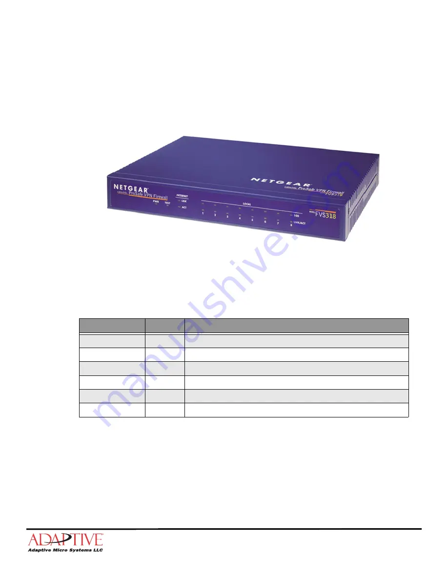
The billboard router creates a firewall protected VPN (Virtual Private Network) inside the 
deluxe remote control cabinet. The router splits the incoming Internet signal from the Internet 
Service Provider’s (ISP) hardware device into eight 10/100 Mbps local ports.

The control cabinet’s PC controllers, UPS’s SNMP / Web card, and the optional diagnostic 
camera’s PoE (Power over Ethernet) device all connect to the router.

Figure 1. Front view of billboard router.

Before you begin

Kit contents

 Not all components are required to be replaced or used, assess the condition of these components and replace 

if necessary.

Tools / Safety equipment needed

„

Full body safety harness with lanyard

Part Number

Qty

Description

30801002

1

8 port 10/100 router with firewall.

N/A

1

Power adapter.

63100008

4

8 inch tie wrap.

65060004

 2

4.5 inch sticky back hook Velcro strip.

65060005

 2

4.5 inch sticky back loop Velcro strip.

1109610109

1

Instructions

Содержание NETGEAR 1109503001SP

Страница 1: ...net The router splits the incoming Internet signal from the Internet Service Provider s ISP hardware device into eight 10 100 Mbps local ports The control cabinet s PC controllers UPS s SNMP Web card and the optional diagnostic camera s PoE Power over Ethernet device all connect to the router Figure 1 Front view of billboard router Before you begin Kit contents Not all components are required to b...

Страница 2: ...er adapter from the control cabinet Loosen the velcro strap around the router Detach the DVI Fiber converter s from the top of the router Remove all tie wraps from the power adapter cord s pathway to the UPS Remove the defective router and power adapter 5 Position and secure the replacement router Attach the appropriate sticky back velcro piece to the top of the router Place the router in the same...

Страница 3: ... router is operating properly if the following can be performed from a remote Internet connection Change or update the message content on the Billboard Access the UPS s web console If applicable access the camera and view the face of the Billboard Notice Do not over tighten the tie wraps Otherwise damage to cord may occur A B C Item Name Description A LOCAL PORTS 1 8 The control cabinet s PC contr...

Страница 4: ...rawer 2 Pull the front handle and slide the KVM drawer out until it stops 3 Lift handle up to open the KVM drawer 4 Press the power on button A 5 Press the 7 selection button B to access PC Controller 1 s desktop Figure 4 Key components of KVM drawer 6 Type http 192 168 0 100 in a web browser s address bar and press Enter 7 At the login prompt type admin for the login and password Figure 5 Router ...

Страница 5: ...asic Settings as shown in the following diagram Figure 7 Router basic settings Click Basic Settings Select No Select Use Static IP Address Enter IP Address Provided by your Internet Service Provider Enter IP Subnet Mask Enter Gateway IP Address Select Use These DNS Servers Enter Primary DNS address Click Apply to save your settings ...

Страница 6: ...REV B 10 Click OK to restart the router Figure 8 Router restart prompt 11 After the router restarts click Logout Figure 9 Router logout 12 Click Yes to exit Figure 10 Router exit prompt 13 Verify router operation see page 3 for details Click Logout ...

Отзывы: