background image

EN

8 - MAINTENANCE

Maintenance includes inspections, checks and interventions which, to prevent interruptions and breakdowns, 

systematically keep the machine lubrication status and the parts subject to wear under control. These operations, 
although simple, must be carried out by Qualified Personnel. 

The machine is designed to minimise routine 

maintenance. It is the operator’s responsibility to assess the status and its suitability for use. We recommend 

stopping the operations and performing maintenance every time operation is not perfect. This will always allow 

maximum efficiency.

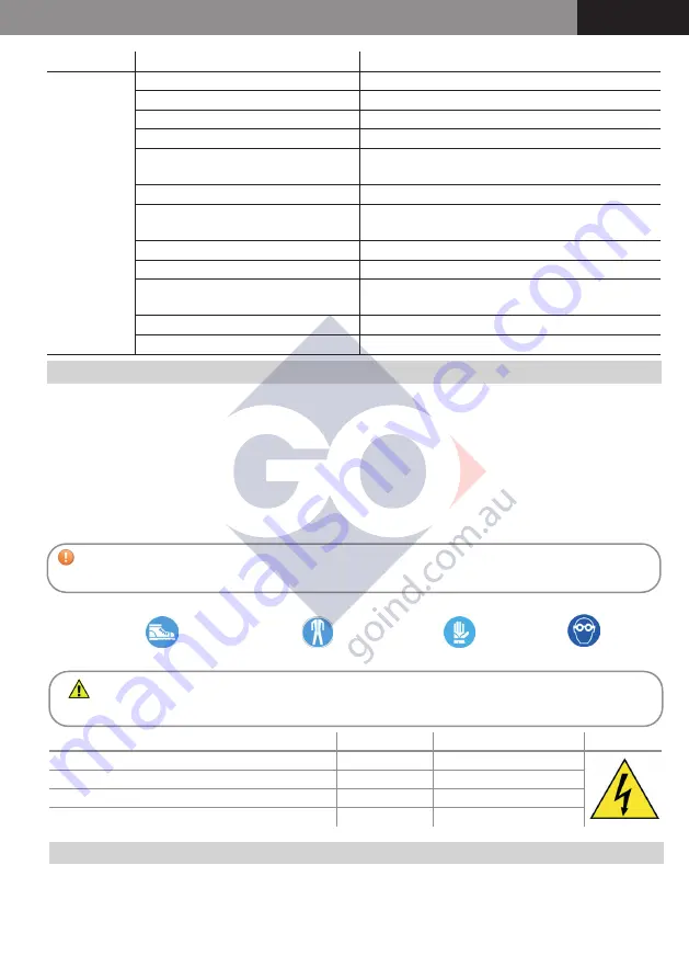
PROBLEM POSSIBLE CAUSE

CORRECTIVE ACTION

LOW OR NO 

FLOW RATE

Low level of liquid in the tank

Fill the tank

Filter dirty or clogged

Clean or replace the filter

Foot valve dirty or clogged

Clean or replace the foot valve

Pipe or dispensing nozzle damaged

Replace the damaged components

Excessive negative pressure to the 

suction line

Make sure there are no leaks or restrictions on the 

suction part (recommended pipes chap. 5.2)

High pressure drops in the circuit

Change the hydraulic discharge configuration

Bypass valve open or blocked

Check the condition of the valve and clean or replace it 

if necessary

Vanes blocked

Check and clean the vanes and their housings

Excessive wear of the vanes or impeller Replace the worn components
Leaks from the gaskets

Make sure the gaskets are properly tightened and not 

worn

Incorrect power supply voltage

Power the pump as specified on the rating plate

Defective motor

Contact the dealer (fault code M2)

9 - DEMOLITION AND DISPOSAL

If the electric pump is to be scrapped, its parts are to be given to companies specialised in disposing of and recycling industrial 
waste, as shown on the table below:

CAUTION! Make sure the pump is disconnected from the power supply and is not in ope-

ration before carrying out any maintenance.


Safety footwear  

Protective clothing 

Protective gloves 

Safety goggles

Always use the appropriate PPE (Personal Protective Equipment):

WARNING! Failure to comply with these requirements will release the manufacturer from any liabi

-

lity resulting from the effects of the Warranty.

MAINTENANCE

FREQUENCY MACHINE STATUS

SYMBOL

Make sure the pipes and couplings are properly connected Every month

Isolation for Maintenance purposes

Check/clean pipes and fittings

Every 12 months

Isolation for Maintenance purposes

Check/clean filter and fittings

Every month

Isolation for Maintenance purposes

Check/clean pump body

Every month

Isolation for Maintenance purposes

Содержание PB 50

Страница 1: ... 48 41011 Campogalliano MO ITALIA Tel 39 059 528128 Fax 39 059 528437 www adampumps com info adampumps com UM032 7 2020 rev 6 PB 50 PB1 50 12 24V PB 60 PB1 60 12 24V PB 85 PB1 85 12 24V ITALIANO lingua originale ENGLISH translation of original instructions IT EN ...

Страница 2: ...ember States relating to the making available on the market of electrical equipment designed for use within certain voltage limits Applicable only for AC powered products the use and maintenance manual must be carefully stored near the machine in an environment protected against humidityandheat Themanualmustaccompanythemachineifsold Itisprohibitedtodamage modifyorremoveany part of the manual USE A...

Страница 3: ... 40 PB1 85 12 V 12V DC 40 480 S2 30 min 85 1 1 70 40 PB 85 24 V 24V DC 32 768 S2 30 min 93 1 1 74 40 PB1 85 24 V 24V DC 32 768 S2 30 min 93 1 1 74 40 IMPORTANT It is essential to have understood the entire instruction manual before perfor ming any operation so as to safeguard operator safety and to avoid potential product damage Storing the manual This manual must be kept intact and fully legible ...

Страница 4: ... the same diameter or a diameter larger than the minimum specified in chapter 3 INSTAL LATION always keep the filter inside the pump clean and regularly inspected 4 3 Storage Prior to its use the pump still in its original packaging should be stored in a dry and protected place in an environment with the conditions described in Section 2 1 Environmental conditions Failure to follow these instructi...

Страница 5: ...itable for operation under negative pressure 5 3 Remarks on the suction lines SUCTION LINE The electric pumps in this manual are self priming and can draw the liquid from a maximum height of 2 metres Caution proper priming and the time required for this can be affected by an automatic nozzle on the discharge line which prevents normal air extraction from the pipe It is therefore always advisable t...

Страница 6: ... and components on the hydraulic line are in good condition and properly sealed and the nozzle is closed the pump can be started After inserting the nozzle into the filling hole switch the pump on gradually release the nozzle lever and start transferring the diesel fuel When you have finished filling close the nozzle and switch the pump off If you are using an automatic nozzle it will automaticall...

Страница 7: ...ed to operate correctly in an industrial electromagnetic environment and staying within the Emission and Immunity limits laid down in the following Harmonised Standards IEC EN 61000 6 2 Electromagnetic compatibility EMC Generic standards Immunity for industrial environments IEC EN 61000 6 4 Electromagnetic compatibility EMC Generic standards Emission standard for industrial environments 7 TROUBLES...

Страница 8: ... and clean or replace it if necessary Vanes blocked Check and clean the vanes and their housings Excessive wear of the vanes or impeller Replace the worn components Leaks from the gaskets Make sure the gaskets are properly tightened and not worn Incorrect power supply voltage Power the pump as specified on the rating plate Defective motor Contact the dealer fault code M2 9 DEMOLITION AND DISPOSAL ...

Страница 9: ...mpered with The product is used in an area with power supply defects voltage changes current phase shift etc The product is used without the supplied suction filter inside or outside the pump Immediately excluded from the warranty are adhesive labels plastic and metal casing keyboards and masks components subject to wear such as blades impellers graphite brushes where present in the motors seals a...

Страница 10: ... PA018 SWIVEL LOCKING PLATE 1 15 11010040200 11010040200 O RING 2015 NBR 1 12V 24V DESCRIPTION QTY 16 82301410100 82301410100 SCREW TC M4 X 8 2 17 VT004 VT004 SCREW TC Ø3 5X16 4 18 12010031000 12010031000 SHAFT SEAL Ø19 1 19 VT046 VT046 SCREW TE M5X12 5 20 OR039 OR039 O RING NBR70 57X2 1 21 OR037 OR037 FILTER SEAL 1 22 17001108 17001108 4M CABLE WITH CLAMPS 1 23 61004600000 61004600000 TIE ROD M5 ...

Страница 11: ... 11 53019030 CABLE GLAND NUT GMP GL 13 5 1 12 83101810000 PLATE WASHER 5x10x1 UNI 6592 2 13 82021810000 SELF LOCKING NUT M5 UNI 7473 2 14 190050210000 SWITCH 22X30 COVER 1 CODE DESCRIPTION QTY 15 PA018 SWIVEL LOCKING PLATE 1 16 VT046 SCREW TE M5X12 FLANGED UNI5541 5 17 11010040200 O Ring 2015 NBR 1 18 71000520 BY PASS VALVE 1 19 61000003 ROTOR Ø45 1 20 71000522 SMALL VANE 5 21 17001097 PIN 3x3x15 ...

Страница 12: ...E Ø5X135 2 8 VT022 HEX SPACER MF M5X25 2 9 PB001 MOTOR COVER IP55 1 10 53015030 CABLE GLAND 1 11 53019030 CABLE GLAND NUT 1 12 83101817100 PLATE WASHER Ø5 2 13 82021810000 SELF LOCKING NUT M5 2 14 190050210000 SWITCH 22X30 COVER 1 CODE DESCRIPTION QTY 15 PA018 SWIVEL LOCKING PLATE 1 16 VT046 SCREW TE M5X12 FLANGED 5 17 11010040200 O Ring 2015 NBR 1 18 71000520 BY PASS VALVE 1 19 61000003 ROTOR Ø45...

Отзывы: