background image

EN • 4

ENGLISH

FRANCAIS

NEDERLANDS

ES

p

A

ño

L

IT

ALIAN

o

DE

u

TSCH

662Y0500 • B

geneRal

energy SaVing

By purchasing this burner, you will be able to make significant 
savings in terms of costs, oil and above all, energy!

we recommend that the heating system is regularly inspected 
and serviced by a qualified heating engineer in accordance with 
DIN 4755.

An indication of the combustion quality and oil consumption can be 
obtained by checking the exhaust gas temperature and the burner 
running times.

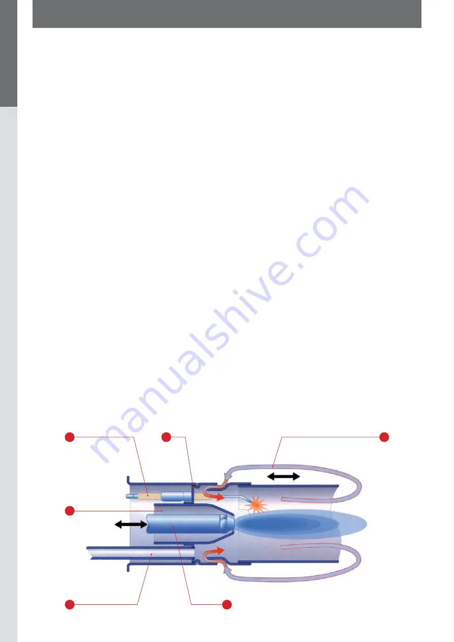
the mixing unit and recirculation 
principle  

A. Air
B.  Ignition electrode
C. Gasket
D. Recirculation
E. Oil
F.  Inspection glass for flame detector

the flame makeS the difference 

Thanks to many years’ experience of developing blue burners, 
we have been able to develop a product that not only meets, but 
far exceeds the sophisticated requirements of modern heating 
technology. In the design and development phase we took an 
innovative route; by combining a new housing with a high-powered 
fan which creates a pressure of 9 - 16 mbar behind the nozzle, 
we have managed to develop a highly efficient oil gasification 
system. This system provides a totally blue flame and an optimum 
soot-free burn, whilst running extremely quietly and is a further 
step towards green technology.

• Exhaust gas temperature

The exhaust gas temperature is measured using a thermometer 
which can be purchased from a specialist shop. The chimney 
sweep’s inspection hole is the ideal measuring point. If the exhaust 
gas temperature appears to increase by more than 30°C, it 
must be assumed that a coating has formed in the combustion 
chamber, which will cause the heating system to run inefficiently. 
If this occurs, clean the boiler and check the burner immediately.

when comparing with reference measurements, make sure that 
the burner running times are the same.

• Operating hours meter

An operating hours meter which records the opening time 
of  the solenoid valve can be used to monitor oil consumption. 
The  system is connected to the electrical supply via the B4 
terminal of the connection plug.

when comparing with reference measurements, allow for the 
respective outside temperature of the year in question.

• Flue gas shut-off valve

Flue gas shut-off valves are occasionally used to prevent excess 
cooling during shut-down. when the system is fully shut down, 
condensation can form in the boiler and the chimney due to 
the interrupted air flow. In addition, hot boiler components may 
reflect back onto the nozzle (carbonization). However, the use 
of a draught limiter or secondary air device can prevent the 
satisfactory ventilation of the chimney and excessive cooling of 
the boiler.

F

D

B

C

A

E

Содержание BMR 33

Страница 1: ...EN 1 ENGLISH FRANCAIS NEDERLANDS espa ol ITALIANO deutsch 662Y0500 B Installation operating and maintenance instructions BMR 33...

Страница 2: ...8 Views gasket 8 Maintenance 9 Maintenance 9 Flame monitoring 9 Troubleshooting 10 Fault causes and solutions 10 Technical documentation 12 Technical data and electrical supply 12 Output table 12 Oil...

Страница 3: ...ith forced draught burners EN 60335 Part 1 Household and similar electrical appliances Safety DIN EN 267 Atomizing oil burners Definitions requirements construction and testing DIN 4755 Oil firing ins...

Страница 4: ...er step towards green technology Exhaust gas temperature The exhaust gas temperature is measured using a thermometer which can be purchased from a specialist shop The chimney sweep s inspection hole i...

Страница 5: ...hermodynamic fuel air mixing Electric motor with operating capacitor Oil pump with built in solenoid valve Automatic oil firing unit for intermittent operation Flame monitoring Ignition transformer Ig...

Страница 6: ...ank and the oil lines must be at least 5 degrees C 5 Make sure that cold outside air cannot be drawn in Burner assembly The BMR blue burner is particularly suitable for installing in standard boilers...

Страница 7: ...ncreased CO2 13 5 the oil pressure must be reduced Check the CO value when the CO2value has been adjusted to 13 14 A CO reading of over 40 mg kWh indicates that the CO2 value has been distorted by an...

Страница 8: ...ize of the mixing system proceed as follows 1 Remove the burner from the heating boiler 2 Loosen the retaining screw on the air intake nozzle and adjust the air intake nozzle Retighten the retaining s...

Страница 9: ...listed in the table on p 13 Flame monitoring Checking the flame detector Use the test socket with an ammeter or multimeter The signal flow should not exceed 5 5 A during the pre purge phase If it doe...

Страница 10: ...trodes incorrectly adjusted to nozzle Adjust as indicated in the manual Incorrect burner settings Check burner settings and readjust if necessary Burner starts and has flame but the flame goes out Dir...

Страница 11: ...Defective coupling between motor and oil pump Replace coupling Kink in oil line Check oil line and replace if necessary External valve to tank system if present may be shut Check the external valve So...

Страница 12: ...M T CF VM1 VM2 AL N PF LOA 14 LOA 14 Automatic oil firing device N Neutral M Burner motor T Ignition transformer VM 1 Solenoid valve 1 VM 2 Solenoid valve 2 AL Warning light CF Flame detector PF Oil p...

Страница 13: ...ank and oil lines Switch off the burner before filling the tank and leave it switched off for approx 3 hours to allow any sediment to settle If the oil lines are not air tight and the tank is running...

Страница 14: ...EN 14 ENGLISH FRANCAIS NEDERLANDS espa ol ITALIANO deutsch 662Y0500 B...

Отзывы: