background image


IMPORTANT CONSUMER INFORMATION SHEET 


The  Consumer  Product  Safety  Commission  estimates  that  about  200,000  injuries  occurred  from  falls  from 
playground  equipment;  which  requires  hospital  emergency  treatment.  Injuries  from  falling  tend  to  be  the  most 
serious of  all playground  injury,  and it  may  be potentially fatal; especially  when it is a head injury. The  ground 
surface under the playground equipment can be an important factor in determining the injury causing potential of a 
fall. A fall onto a shock absorbing surface is less likely to cause serious injury in comparison to a fall onto a non 
shock absorbing hard surface. Never place playground equipment on hard surface such as concrete, asphalt, rocks, 
grass may appear to be acceptable, but in heavy traffic area, it may quickly turn into hard packed earth. Fine sand, 
wood chips, shredded bark are acceptable shock absorbing surface, when installed at a sufficient depth under the 
playground equipment, it must be maintained properly under and around the perimeter of playground equipment. 
 

Table  below  lists  the  maximum  height  from  which  a  child  would  not  be  expected  to  sustain  a 
life-threatening injury to the head, when falling onto the loose fill surface materials, provided that 
these materials are installed and maintained at 6, 9 and 12 inches deep. However, consumers should 
recognize that no matter what type of surface material is used, it can not prevent all injuries due to 
falls. 


FALL HEIGHT IN FEET FROM WHICH 

A LIFE THREATENING HEAD INJURY WOULD NOT BE EXPECTED 

MATERIAL 

6INCH DEPTH 

9INCH DEPTH 

12INCH DEPTH 

Double shredded bark mulch 

10 

11 

Wood Chips 

12 

Fine Sand 

 
We recommend that surfacing material as per table above should extend a minimum of 6ft in all direction from the 
perimeter  of  the playground equipment.    In certain cases,  a child may deliberately  jump from a  moving  swing. 
Therefore, any shock absorbing material should extend in the front and rear of swing a minimum of 2 times the 
height  of  the  pivot  point;  this  height  is  determined  by  measuring  from  a  point  directly  beneath  the  pivot  on  the 
supporting structure. 
 
Please note this information is intended to assist in comparing the relative shock-absorbing properties of various 
materials.  No  particular  material  is  recommended  over  another.  Every  material  is  only  effective  when  properly 
maintained. Material should be maintained and  replenished periodically after inspection  by user, to  maintain the 
correct depth necessary for your equipment. 
 
Note:    The maximum fall height for this product is 6 feet.    The minimum ground clearance between the bottom 
of the suspended plays and the playing or ground service must be 8 inches. 


Содержание S001S

Страница 1: ...nual Model S001S Un IMPORTANT Read all instructions carefully before using this product Retain this owner s manual for future reference The specification of this product may vary from this photo subje...

Страница 2: ...Y INSTRUCTIONS 2 CARE MAINTENANCE INSTRUCTION 4 PARTS LIST 6 ASSEMBLY INSTRUCTIONS 10 Customer service number 0800 422 274 MON FRI 8AM 5PM SAT SUN 9AM 4PM Marketed By The Warehouse LTD 26 The Warehous...

Страница 3: ...uipment sits on level ground To prevent serious injury to children the playground equipment must not be used until properly assembled and anchored Do anchor all playground equipment Do not install ove...

Страница 4: ...ially hazardous to users Verify that suspended climbing ropes chain or cable are secured at both ends and verify that suspended climbing ropes chain or cable cannot be looped back on itself Instruct c...

Страница 5: ...iodically during use Replace when necessary Plastic components should be replaced every three years DISPOSAL INSTRUCTIONS When it is time to dispose of the playground equipment please use care when di...

Страница 6: ...at these materials are installed and maintained at 6 9 and 12 inches deep However consumers should recognize that no matter what type of surface material is used it can not prevent all injuries due to...

Страница 7: ...re If you intend to install Not included Anchor this is needed Flat Head and Philips Wrench Head Screwdriver included Not included Allen Wrench included Parts list for main frame assembly A1 LEF TOP B...

Страница 8: ...6 SPRING WASHER 4 PCS Parts list for swing seat J1 PVC COVERED CHAIN PREASSEMBLED 4 PCS J3 EYE BOLT WITH ATTACHMENT BOLT PREASSEMBLED 4 PCS J4 EYE BOLT PREASSEMBLED 4 PCS K1 SWING SEAT 2 PCS Hardware...

Страница 9: ...ride assembly L4 BRACKET 1 PC L5 BRACKET CLAMP 1 PC L6 WASHER 4 PCS N2 BOLT 5 16 25 2 PCS N8 NYLON NUT 5 16 2 PCS N14 PLASTIC CAP 2 PCS Hardware used for glide ride assembly N1 BOLT 1 4 35 4 PCS N2 BO...

Страница 10: ...C X5 SLIDE FRONT SUPPORT 1 PC X6 SLIDE LADDER STEPS 2 PCS Y2 SLIDE 1 PC Hardware used for slide assembly Y1 PLASTIC CONNECTOR 2 PCS Z1 BOLT1 4 35 6 PCS Z2 BOLT1 4 60 2 PCS Z3 BOLT1 4 100 2 PCS Z4 WASH...

Страница 11: ...sphalt packed earth or any other hard surface A fall onto a hard surface can result in serious injury to the user TIGHTENING NUTS BOLTS Do not over tighten the nuts and bolts when you are assembling y...

Страница 12: ...11 Step 1 Insert A1 into the other end of A2 secure with B1 B5 B4 and B3 HINT Please make sure that concave hole faces down...

Страница 13: ...12 Step 2 Insert small end of A4 into the socket at the end of A1 align holes on them Secure with B1 B5 B4 and B3 Then attach the other two pieces of A4 on the other side to A2 the same...

Страница 14: ...13 Step 3 Secure with B1 B5 B4 and B3 Secure with B2 B6 B4 and B3 Insert A5 into A4 align holes on them Attach A6 to A5 Repeat above to assemble the other A7 to A5 that is attached to the end of A2...

Страница 15: ...14 Step 4 Insert J3 into holes on A1 A2 Secure it with J8 J9 and J6 Step 5 J4 and K1 are PRE ASSEMBLED if you find it loosely please follow below step Attach K1 to J4 Secure with J7 J9 and J6...

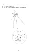
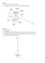
Страница 16: ...w driver to tighten the N3 and N8 Step 7 Attach M5 to L1 Secure N5 N13 M1 M2 and L1 are PRE ASSEMBLED if you find it loosely please follow below step Attach M1 to the top of L1 and then align holes on...

Страница 17: ...N2 and N11 Step 9 Insert 2xM3 into L2 then attach L3 to L2 with N6 lightly secure N6 with N9 Do not tighten completely Attach the other L1 L2 and L3 by the as way as described above once this is done...

Страница 18: ...17 Step10 Attach M4 to L2 Secure using N1 N9 N7 and N11 Step 11 Attach X5 to Y2 Secure using Z7 and Z1 Attach X4 to Y2 NOTE Make sure that the bolt holes face up...

Страница 19: ...d in position Step 13 Insert the end of X4 into X1 secure using Z2 Z4 and Z5 In the same way fix the other end of x4 with X2 Insert Z1 into Z4 and insert into X1 X2 and X3 as shown Insert Z8 into Z4 a...

Страница 20: ...19 Step 14 Attach Y1 to X1 and A7 secure using Z3 Z7 and Z4 Z5 Step 15 Go back to secure Z3 and Z5 to X1 now Tighten all screws...

Страница 21: ...ment is firmly anchored cementing is usually recommended When equipment is cemented do not bury the legs more than three inches below the ground surface This will ensure sufficient space remains under...

Страница 22: ...use shovel to crave out the lower part of the hole to create a large diameter hole bottom Place 2 inches brick or gravel bed as shown in drawing below Use about 45lb of concrete per leg Cover concret...

Отзывы: