P94
Dual ESC/Mixer Multi-controller
Installing the P94
Because of the high power of the P94 Multi-controller, care should be paid to the installation of the unit.
Each ESC circuit can deliver 20A continuously and the wiring installation should be designed with that in
mind.
Fig #4 shows a basic installation. The length of all wires should be kept to an absolute minimum, but not to
The fuse must be sized to be as small as possible without causing nuisance tripping. A 40A fuse (maximum)
should be used to protect the unit.
If more than one battery is being used for the installation, they should be connected in parallel. This is best
done by using a P103 Parallel Power Board. This will handle up to 15v @ 20A and prevents any possibility
of one battery discharging into the other and causing damage or even fire to the wiring. See Fig #6. If you
are using >15v then first connect the two battery positive terminals together and the two battery negative
terminals together and then connect each of the joined pairs to the P92 etc.
When connecting the motors, suitably rated cable must be used and the lengths kept as short as possible.
2
We recommend multi-strand cable of at least 2mm (16AWG). The wiring of the two motor connections is
reversed with respect to each other, so that they rotate in opposite directions when ahead or astern
commands are given. It is also recommended that the outputs from the ESCs are individually fused. P95
is ideal for this purpose; See Figs #1 & #2. Each fuse must be no more than 20A.
Terminal block TB1 is used for one motor or the bow thruster, and TB2 is used for the other motor or the
stern thrusters (depending on the operating mode). Do NOT allow the two heat-sink tabs to touch each
other or touch any other power wiring. Additional cooling in the form of extra heat-sinks or water-carrying
tubes can be fitted to the aluminium tabs, but they must remain electrically isolated from each other.
When connecting the receiver to other servos or speed controllers there are two “straight-through”
connections on the P94 in the form of 3-pin headers. See the Schematic Drawing on the Front Page of this
manual. These eliminate the need for Y-leads from the receiver outputs. H1 would be used conventionally
to connect the steering servo, while H2 will supply the throttle signal (unmixed) to a third electronic speed
controller e.g. for a central motor. Header pins H2 can also be used to connect a digital engine sound unit
to the system e.g. ACTion P1 0. The sound will then follow the throttle stick input and will not be affected
1
by any degree of mixing.
01248 719353
The latest version of P94 has a switch-mode voltage regulator, or Battery Eliminator Circuit (BEC) fitted.
This takes power from the main motor battery/batteries and reduces it to 5v to operate the logic circuit in
P94 and to feed the power to the receiver, also @ 5v.
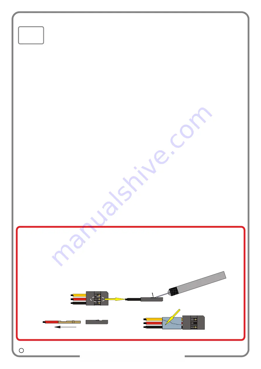
Unless you want to run the receiver from a
seperate battery (or the flylead from P92/P102/P107) then you MUST remove the red wires
from the two leads marked T and S.
If you leave either of them connected then the receiver will be at
risk of serious damage due to being “fed” two different voltages at the same time. You can modify the
plugs easily like this:
2
1
3
Slightly lift tab
Bend and tape back RED lead
Withdraw RED (Positive) lead
Pointed blade
White/Yellow
ESC receiver lead
Red
Black
the extent that they are tight, a small amount of slack will reduce the risk of them coming loose in use.
C 2023 Action R/C Electronics


