33
Eubank Wall Mount Heat Pump I&O Manual
05/2023 Rev.2
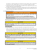
inch clearance is required around the duct extensions. The duct extensions must be constructed of
galvanized steel with a minimum thickness of .019” as per the NFPA standards 90A & 90B.
9. Check the fit of each sleeve to its mating flange for possible air leaks. Apply silicone sealer to close
any gaps. Install the air return and supply grilles.
10. To minimize sound transmission, a latex based, insulating foam seal may be applied between the
duct extensions and the frame for the wall openings. NOTE: DO NOT USE THE FOAM ON ANY
UNITS WITH ELECTRIC RESISTANT HEATERS.
3.8 Electrical Connections
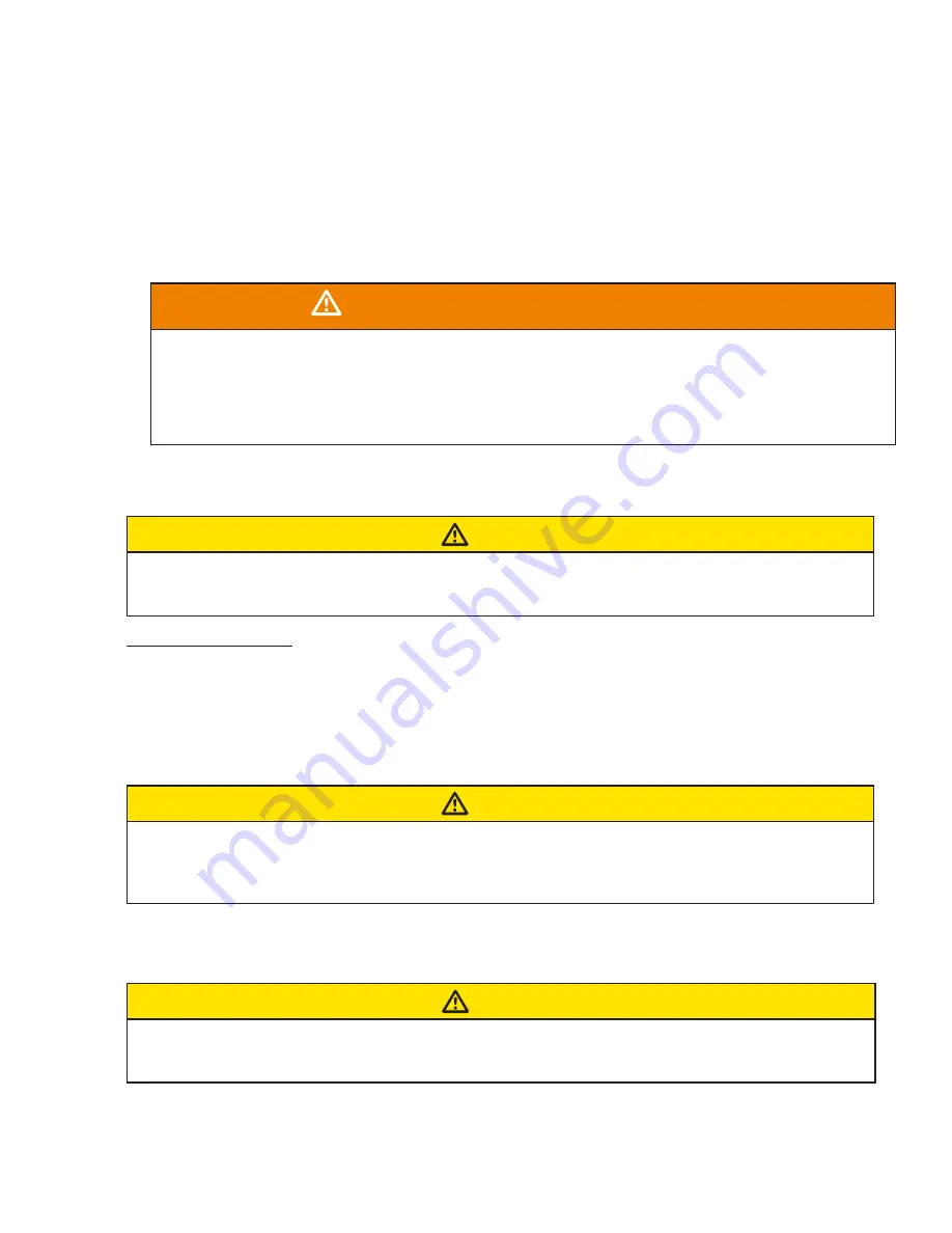
WARNING - ELECTRICAL SHOCK HAZARD
Failure to follow safety warnings exactly could result in serious injury, death, and/
or property damage.
Turn off electrical power at fuse box or service panel BEFORE making any
electrical connections and ensure a proper ground connection is made before
connecting line voltage.
All electrical work must meet the requirements of local codes and ordinances.
Work should be done
only by qualified persons.
CAUTION
This Eubank Heat Pump may incorporate an internal crankcase heater for compressor
protection.
The crankcase heater must be energized for at least 24 hours prior to
starting the compressor.
High Voltage Wiring
The power supply should have the proper voltage, phase, and ampacity for the selected model.
1. Refer to the electrical data on the data sticker on the unit for field wiring requirements of the unit.
Size the incoming power supply lines and the fuse(s) or HACR breaker(s) according to requirements
described in the National Electric Code. Run the power conductors through the knockouts on the side
or back of the unit. Use appropriate conduit and strain reliefs.
CAUTION
Note: Power supply service must be within allowable range (+10% - 5%) of rated
voltage stamped on the unit rating plate. To operate nominal 230/208V unit at 208V,
change the transformer line tap from 240V to 208V following the instruction on wiring
label in unit.
2. Connect the wires to the input side of the internal breaker (L1 & L2 for single-phase units; L1, L2,
& L3 for three phase models).
CAUTION
CAUTION! This system contains components that require phasing for correct rotation.
Failure to observe rotation and correct on start-up will cause damage not covered
by the Eubank
®
Warranty.


