ACP MXP5201 Скачать руководство пользователя страница 23

21

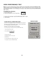
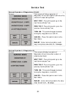
Manual Operation of Magnetrons #1 & #2 

Screen

This screen will allow operation of 

Magnetron #1 and #2 together and show the 

number of amps being drawn. 

NEXT TEST: 

 Press this pad to go to the 

next Service Mode Test 

PREV TEST:

  Press this pad to go to the 

previous Service Mode Test 

TURN ON: 

 This pad will toggle between 

turning the magnetrons on and off. 

CANCEL:

 Press this pad to return to the 

Main Menu 

RANGE:

 Under normal operation, each 

mag’s amp draw should be 

5 – 12 amps.

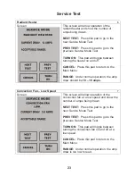
Manual Operation of Magnetron #1 

Screen

This screen will allow operation of 

Magnetron #1 and show the number of 

amps being drawn. 

NEXT TEST: 

 Press this pad to go to the 

next Service Mode Test 

PREV TEST:

  Press this pad to go to the 

previous Service Mode Test 

TURN ON: 

 This pad will toggle between 

turning the magnetron on and off. 

CANCEL:

 Press this pad to return to the 

Main Menu 

RANGE:

 Under normal operation, the amp 

draw should be 

5 – 12 amps.

2

3

Service Test

Содержание MXP5201

Страница 1: ...______________ Service Manual High Speed Combination Oven AXP5201 P1333603M MXP5201 50 Hz October 2010 16400004 Rev 1 P1333604M AXP5203 P1333608M MXP5203 P1333609M ...

Страница 2: ...pecifications 6 Oven Construction 7 12 Oven Performance Test 13 Troubleshooting 14 18 Display Diagnostics 19 Service Test 20 27 Touch Screen Calibration 28 Component Test Procedures 29 30 Quick Start Reference Guide 31 34 EZ Card Programming 35 Wiring Diagram 36 Schematic Diagram 38 ...

Страница 3: ...s equipped with the proper tools parts testing instrumentsandtheappropriateserviceinformation ITISTHETECHNICIANSRESPONSIBLITYTOREVIEWALL APPROPRIATESERVICEINFORMATIONBEFOREBEGINNINGREPAIRS WARNING Toavoidriskofseverepersonalinjuryordeath disconnectpowerbeforeworking servicingonappliancetoavoid electrical shock Recognize Safety Symbols Words and Labels DANGER DANGER Immediatehazardswhich WILL resul...

Страница 4: ...ng an authorized ACP servicer or ACP ComServ Service Support if service is required after warranty expires PRECAUTIONS TO AVOID POSSIBLE EXPOSURE TO EXCESSIVE MICROWAVE ENERGY A DO NOT attempt to operate this oven with the door open since open door operation can result in harmful exposure to microwave energy It is important not to defeat or tamper with the safety interlocks B DO NOT place any obje...

Страница 5: ...cord or plug in water 13 Keep cord AWAY from HEATED surfaces 14 DO NOT let cord hang over edge of table or counter 15 See door cleaning instructions on page 4 16 To avoid risk of fire in the oven cavity a DO NOT overcook food Carefully attend oven when paper plastic or other combustible materials are placed inside the oven to facilitate cooking b Remove wire twist ties from paper or plastic bags b...

Страница 6: ... skin of potatoes tomatoes and similar foods before cooking with microwave energy When skin is pierced steam escapes evenly 11 Do not heat sealed containers or plastic bags in oven Food or liquid could expand quickly and cause container or bag to break Pierce or open container or bag before heating 12 Do not heat baby bottles in oven 13 Baby food jars shall be open when heated and contents stirred...

Страница 7: ...RPM Radiant heater 3000 Watts Convection heater 2000 Watts Combination 5000 Watts Dimensions Cabinet in cm 25 63 5 cm Width 20 25 51 cm Height 25 625 65 cm Depth includes bracket on back Oven Interior in cm useable space Width 16 0 41 cm Height 7 75 20 cm Depth 15 0 38 cm Weight lbs kg Uncrated 150 lbs 68 kg SPECIFICATIONS AXP5203 MXP5201 MXP5203 Crated 175 lbs 79 kg Minimum Temperature Rise T 22 ...

Страница 8: ...6 Air Filters Top Outer Panel Left Outer Panel Outercase Back OVEN CONSTRUCTION PANELS TOP SIDE Right Outer Panel Torx T 15 Torx T 15 Door AXP OVEN CONSTRUCTION ...

Страница 9: ...play Knob Collar Knob Data Key Board Data Key Board Holder OVEN CONSTRUCTION CONTROL PANEL ASSEMBLY Data Key Plug Caution Do not handle touch screen display by the sides This may damage the display circuitry Handle using the corners Bezel Filter Board OVEN CONSTRUCTION ...

Страница 10: ...e Limiter Temp Sensor RTD Radiant Power Supply Board 24 VDC OVEN CONSTRUCTION Circuit Boards Power Relay Limiter Triac Thermocouple Temp Sensor RTD Cooling Fans Convection Motor Cavity TCO Snubber Note If Main Fuse F1 is blown replace Relay Monitor Board Power Relay Interlock Switch Assembly Cavity TCO OVEN CONSTRUCTION ...

Страница 11: ...ron TCO s Temp Sensor RTD Convection Switch Primary Triac TR2 Triac TR1 Magnetron 1 OVEN CONSTRUCTION HV Transformers Magnetrons Fuses Sensor Triac s Magnetron TCO s Capacitor Diodes Line Filter Capacitor Diode Right Side Capacitor Diode Left Side Magnetron 2 Magnetron 2 Convection Heater Note If Main Fuse F1 is blown replace Relay Monitor Board Power Relay Interlock Switch Assembly Line Filter OV...

Страница 12: ...lever for proper switch activation 3 Tighten mounting screws 4 Preheat oven to set temperature and verify switch adjustment settings and function Note To ensure proper switch adjustment the switch mounting MUST be tightened after each adjustment prior to testing the door alignment Removal 1 Remove switch assembly mounting screw 2 Push switch assembly 1 2 inch 13mm towards back of oven 3 Twist moun...

Страница 13: ...11 See Detail Below Antenna Motor Cam Gear Assembly Antenna Rivet Plastic Alignment Arrows Gear Assembly Antenna Rivet Plastic Antenna Motor Cam Note Plastic Rivet cannot be reused OVEN CONSTRUCTION ...

Страница 14: ... beep remove test bowl from oven PREHEAT MENU 4 Press Pad 3 twice for 33 seconds 5 Press Start 7 Press OFF to return to PREHEAT MENU See page 13 for Oven Performance Test procedure 245 C Note To run Oven Performance Test the oven cavity must be at room temperature and the display must read MICROWAVE ONLY mode See below using oven as a microwave oven If MICROWAVE ONLY is not in display you must go ...

Страница 15: ...e and record the temperature T1 3 Place test container of water in the center of oven cavity and close door 4 Heat the water for a 33 second full power cycle NOTE Use a digital watch or a watch with a second hand for ovens with electromechanical timers 5 At end of the cycle remove test container Using the thermometer stir water for five to ten seconds and record temperature T2 6 Subtract the start...

Страница 16: ...re Connection 9 Open Cavity TCO Yes Error Code Appears 1 Refer To Display Diagnostics Page 19 PLUG OVEN IN No No PREHEAT TEMP 270 C PRESS TO PREHEAT PROGRAM CHANGE TEMP PREHEAT TEMP 270 C PROGRAM CHANGE TEMP 2 Clear Error History After Oven is Repaired NORMAL DISPLAY NORMAL DISPLAY POWER UP CONDITION Go to PREHEAT Condition PRESS TO PREHEAT Operational Code Appears 1 Refer To Operational Codes Pag...

Страница 17: ...emp Sensor RTD Radiant 9 Inoperative Main Board 10 Broken or Loose Wire 11 Open Cavity TCO OVEN PREHEATING PREHEAT TEMP 270 C PROGRAM CHANGE TEMP MENU BACK MANUAL COOK 1 2 3 4 5 6 READY PREHEAT TEMP 270 C PROGRAM MANUAL COOK MENU CHANGE TEMP PREHEAT CONDITION Indicates Rising Temperature NORMAL DISPLAY NORMAL DISPLAY NORMAL DISPLAY Indicates Temperature Reached 3 Inoperative Fuse F 6 4 Inoperative...

Страница 18: ... Inoperative Power Relay 2 Inoperative Primary Switch 3 Inoperative Secondary Switch 3 Fuse F3 4 Fuse F4 5 Inoperative Main Board 6 Inoperative Capacitor 7 Inoperative Diode 8 Inoperative H V Transformer NEXT TEST PREV TEST CANCEL TURN ON MAGNETRON 1 5 12 AMPS MAGNETRON 2 5 12 AMPS SERVICE MODE OVEN INFORMATION DISPLAY VERSION 0 39 MAIN VER 0 46 EE 0 3 DOOR CYCLES 20 156 TUBE HRS 2156 EE 255 NEXT ...

Страница 19: ...OOR PLACE FOOD CLOSE DOOR IN OVEN During oven operation the display may indicate one of the following 1 When you press the pad knob to preheat the oven the display indicates 2 During cooking the oven display indicates 1 After food is placed in the oven the door is closed the display indicates 1 After food is placed in the oven the door is closed the display indicates See component test procedures ...

Страница 20: ...k Switch 4 Inoperative Secondary Interlock Switch 5 Secondary Interlock Switch out of Adjustment 6 Broken or Loose Wire Connection 7 Inoperative HV System Magnetron See component test procedures section for testing procedures and results CHASSIS MEMORY ERROR 1 Unplug the oven and remove right side panel 2 Disconnect the data key board connector from the display board Figure 1 3 Plug the oven in Se...

Страница 21: ... Unplug Plug oven in G 2 Magnetron TCO Perform service test Magnetron 1 2 G 2 Cooling Motor Perform service test Cooling Fan H 0 Signal Missing Plug disconnected from J1 on main board H 1 Main Board Set Point Incorrect Unplug Plug oven in H 2 Main Board Replace main board H 3 Main Board Replace main board M 0 Current Sense Low Amps Perform service test Magnetron 1 2 M 1 Magnetron 1 Low Amps Perfor...

Страница 22: ...ntrol boards and information about door cycles and tube hours NEXT TEST Press this pad to go to the next Service Mode Test PREV TEST Press this pad to go to the previous Service Mode Test CLEAR INFO Press this pad to reset the Door Cycles and Tube Hours back to zero EXIT Press this pad to return to the ovens Main Menu Hidden Pad 1 1 Press OFF pad until PRESS TO PREHEAT appears 2 Press Hidden Pad 3...

Страница 23: ...s this pad to return to the Main Menu RANGE Under normal operation each mag s amp draw should be 5 12 amps Manual Operation of Magnetron 1 Screen This screen will allow operation of Magnetron 1 and show the number of amps being drawn NEXT TEST Press this pad to go to the next Service Mode Test PREV TEST Press this pad to go to the previous Service Mode Test TURN ON This pad will toggle between tur...

Страница 24: ...this pad to return to the Main Menu RANGE Under normal operation the amp draw should be 5 12 amps Convection Heater Screen This screen will allow operation of the convection heater and show the number of amps being drawn NEXT TEST Press this pad to go to the next Service Mode Test PREV TEST Press this pad to go to the previous Service Mode Test TURN ON This pad will toggle between turning the heat...

Страница 25: ...urn to the Main Menu RANGE Under normal operation the amp draw should be 10 16 amps Convection Fan Low Speed Screen This screen will allow operation of the convection fan at a low speed and show the number of amps being drawn NEXT TEST Press this pad to go to the next Service Mode Test PREV TEST Press this pad to go to the previous Service Mode Test TURN ON This pad will toggle between turning the...

Страница 26: ...this pad to return to the Main Menu RANGE Under normal operation the amp draw should be 0 6 2 6 amps Cooling Fan Screen This screen will allow operation of the cooling fan show the number of amps being drawn NEXT TEST Press this pad to go to the next Service Mode Test PREV TEST Press this pad to go to the previous Service Mode Test TURN ON This pad will toggle between turning the cooling fan on an...

Страница 27: ...to the Main Menu RANGE Under normal operation the amp draw may be to low to read RTD Status Screen This screen will show the temperatures being reported to the RTD s in the oven The maximum temps seen by the controller are also recorded for diagnostic purposes NEXT TEST Press this pad to go to the next Service Mode Test PREV TEST Press this pad to go to the previous Service Mode Test CANCEL Press ...

Страница 28: ...PREV TEST Press this pad to go to the previous Service Mode Test CANCEL Press this pad to return to the Main Menu Error List Screen This screen will show a description of the types of errors that can occur NEXT TEST Press this pad to go to the next Service Mode Test PREV TEST Press this pad to go to the previous Service Mode Test CANCEL Press this pad to return to the Main Menu 12 13 Service Test ...

Страница 29: ...nce through the history of the error codes 1 10 CANCEL Press this pad to return to the Main Menu Voltage Switching Screen This screen will show the line voltage detected by the oven NEXT TEST Press this pad to go to the next Service Mode Test PREV TEST Press this pad to go to the previous Service Mode Test CANCEL Press this pad to return to the Main Menu Note To clear codes Press and hold Pad 1 un...

Страница 30: ...splay The Square will move to adifferent location on the Display 6 Press Directly On the small Square in the Display again until the 7 Press the 0 Pad 8 A small box will appear in the top left square Press on each box and the small square will follow After you have touched all the boxes and the small square followed you go to step 9 9 Press the 0 pad to return to the Stand by screen Hidden Pad squ...

Страница 31: ... no voltage check H V board and wiring Capacitor Discharge Capacitor Remove wires from capacitor terminals and connect ohmmeter set on highest resistance scale to terminals Also check between each terminal and capacitor case Between Terminals Meter should momentarily deflect towards zero then return to over 5 MΩ If no deflection occurs or if continuous deflection occurs replace capacitor Terminal ...

Страница 32: ...0 to terminal 1 coil 0 1 2 4 6 8 Approximately 6 to 7 M NOTE Analog meter is recommended for measurement NOTE If using a digital meter it must contain a battery of 6 volts minimum Wire harness High voltage board to display module harness Test continuity of wires Indicates continuity Ω Line Voltage ST2 GN YL OR BU Disconnect ST2 Fan should operate at High Speed Primary switch Secondary switch Monit...

Страница 33: ... the dial clockwise to scroll through menu options 2 The current menu selection will be highlighted 3 To select menu item press dial The icons below will be used throughout this guide to indicate when menu navigation other than the dial is necessary TOUCH SCREEN KEYPAD Getting Started Using MANUAL COOK To cook food using a specific entered time and power level 1 After oven has preheated Select MAN...

Страница 34: ...erase one character at a time 4 Highlight SAVE button and press dial to select when item is complete If you do not wish to save the entry press the back button to return the oven to Program Edit without saving 5 Press BACK button to return to READY display ACCESSING THE PROGRAM MENU 1 To access the PROGRAM MENU select the BACK button on the main menu screen 2 Then select PROGRAM from the READY scr...

Страница 35: ...owave power 7 Input desired fan speed 8 Input desired IR heating setting 9 Press SAVE button on screen If necessary repeat steps 4 through 8 for stages 2 3 and 4 10 Enter Item Names using letters on keypad and touch SAVE TOUCH SCREEN COOKING PROGRAM MENU KEYPAD 245 245 245 245 245 C 245 245 245 245 245 245 Push Push Push 245 245 245 C Push Push Push SAVE SAVE SAVE SAVE SAVE ASSIGNED NAME Mozz Ch S...

Страница 36: ...f the oven Refer to Owner s Manual for complete cleaning instructions High Speed Commercial Combination Oven KEYPAD Option Setting Name Options Single digit entry 1 Digit Entry Double digit entry 1 Level 2 Levels 2 Menu Setting 3 Levels Manual cooking allowed 3 Manual Lock Manual cooking not allowed Changes to programs allowed 4 Program Lock Password needed Opening door resets timer 5 Door Open Op...

Страница 37: ...Next Option 5 Select the desired operation by highlighting Transfer card to oven or Transfer oven to card with the knob 6 Press the Start pad to begin the transfer The screen will indicate transferring and indicate done when transfer is complete 8 Remove EZCard and close the protective cover Note You can exit from programing the oven by pressing off keypad 7 Press the SAVE pad to complete the proc...

Страница 38: ...H SCREEN DISPLAY PRIMARY INTLK SWITCH TERM BLOCK TERM BLOCK NO COM NC RADIANT RTD WH THERMOCOUPLE MAGNETRON 2 YL BR BU GY OR VT VT SECONDARY INTLK SWITCH NO COM NC GY OR VT BR RD YL VT YL OR BU OR BK VT FUSE F6 BU GY FUSE F5 BU BK GY GY VT VT WH YL RD WH BK YL BK YL FUSE F2 F3 F4 BR BR FUSE F1 OR BK OR RD BU RD BU RD RD RD YL YL YL YL MAGNETRON 1 BR BU RD RD 1 G 2 GN YL OR BU VT OR CONVECTION HEAT...

Страница 39: ... TERM BLOCK TERM BLOCK NO COM NC RADIANT RTD WH THERMOCOUPLE MAGNETRON 2 YL BR BU GY OR VT VT SECONDARY INTLK SWITCH NO COM NC GY OR VT BR RD YL VT YL OR BU OR BK YL RD GY GY VT VT WH YL RD WH BK YL BK YL FUSE F2 F3 F4 BR BR FUSE F1 OR BK OR RD BU RD BU RD RD YL YL YL YL MAGNETRON 1 BR BU RD 1 G 2 GN YL OR BU VT OR CONVECTION HEATER TRIAC TR3 GY BK OR GY BU RD OR BK BU RD WH BK YL OR RD CONVECTION...

Страница 40: ...J2 3 J2 5 GND 24VDC U17 20025502 J14 2 J9 1 J8 7 J9 2 J4 1 G T1 T2 TR1 J14 1 J8 8 U19 U8 K1 G T1 T2 40ATR3 G T1 T2 40ATR4 G T1 T2 TR2 J9 3 J9 4 SECONDARY INTERLOCK PRIMARY INTERLOCK U10 U15 J5 1 J5 3 J5 4 J5 2 K2 J5 5 2 4 0 1 6 8 MONITOR INTERLOCK G T1 T2 40ATR2 J8 2 J8 3 J8 1 U11 K3 J6 3 J6 1 J6 2 200 230 CONTROL U14 K4 J6 6 J6 4 J6 5 200 230 G T1 T2 40ATR1 J8 5 J8 6 J8 4 F3 T2 TO HV CIRCUIT LEFT...

Страница 41: ... 2 J9 1 J8 7 J9 2 J4 1 G T1 T2 TR1 J14 1 J8 8 U19 U8 K1 G T1 T2 40ATR3 G T1 T2 40ATR4 G T1 T2 TR2 J9 3 J9 4 SECONDARY INTERLOCK PRIMARY INTERLOCK U10 U15 J5 1 J5 3 J5 4 J5 2 K2 J5 5 2 4 0 1 6 8 MONITOR INTERLOCK G T1 T2 40ATR2 J8 2 J8 3 J8 1 U11 K3 J6 3 J6 1 J6 2 200 230 CONTROL U14 K4 J6 6 J6 4 J6 5 200 230 G T1 T2 40ATR1 J8 5 J8 6 J8 4 F3 T2 TO HV CIRCUIT LEFT MAGNETRON T1 TO HV CIRCUIT RIGHT MA...

Страница 42: ...50 Hz High Speed Combi AXP5201 AXP5203 October 2010 16400004 Rev 1 ...

Отзывы: