43
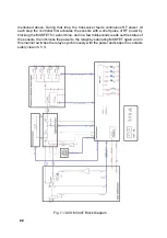
case, the KS2 relay on the Capacitors board is used to connect the input sensor output
to the input of the matching circuit (L-network), so that the sensor measures the anten
-
na impedance, transformed by the matching circuit.
In tuning mode, the input RF power is fed through the 27 Ohm/100W resistor and
primary windings of two current transformers, TA1 and TA2, to two branches - one to
the input of the matching circuit and another to a reference resistor 50 Ohm/15W,
which is compared to the input impedance of the L-network, thus forming a RF
impedance bridge.
NOTE
The transformers TA1 and TA2 are located on the
Capacitors board, while the block diagram shows them
with their primary windings only.
The secondary windings of TA1 and TA2 feed to the input sensor RF voltages,
proportional to the RF currents in the two branches - the reference 50 Ohm/15W
resistor and the anenna impedance transformed by the matching circuit. The
relation of amplitudes and phases of these two signals represents unambiguously
the complex value of the antenna impedance transformed by the matching circuit.
By comparing properly selected parts of these two signals and their combinations
by module and by phase, the sensor produces the following three logic output
signals, characterizing the position of the antenna impedance transformed by the
matching circuit, towards the target of the tuning, i.e. towards the point (50+j0) Ohm,
on the complex impedance plane:
-
“R” logic output – shows whether the real part of the transformed impedance is
above or below 50 Ohm;
-
“G” logic output – shows whether the real part of the transformed admittance is
above or below 1/50S (20mS);
-
“PH” logic output – shows whether the phase sign of the transformed imped
-
ance is inductive or capacitive.
The three logic signals in question, “R”, “G”, “PH”, and the detected forward and re
-
flected power “fwd” and “rfl” (from the input of the matching circuit) are the main sourc
-
es of information, which are fed by the input sensor to the Control board during the
full-tuning process. They are processed by the Control board, which provides the tuner
operation algorithm (including the tuning algorithm).
As mentioned above, in tuning mode, the input RF power is mainly fed to the 27
Ohm/100W resistor. The INPUT SWITCH MOSFET is normally saturated (high level
on gate from *RFON signal), so the RF current is diverted to the ground through its
drain-source channel. In this state, almost all input RF power is dissipated by the 27
Ohm/100W resistor and nothing is fed to the matching network. When the MOSFET
is saturated, the control system can switch over the tuner relays without a risk of relay
contact arcing and deterioration, while the tuner input impedance is kept below SWR
of 2:1.
The process of full tuning runs in a number of steps (S 5.1) and at each step the Con
-
trol board enables and blocks the RF power through the MOSFET INPUT SWITCH
Содержание ACOM 04AT
Страница 1: ...1 ...
Страница 57: ...2 2 ...


