background image

Part 2. Usage

Combo Cat6 KVM Usage

2.1 KVM Button

Power ON

¦

Turn off all servers and KVM switches

¦

Make sure all cables / connectors are properly connected

¦

Recommend Power ON sequence is monitor, KVM switch finally computer

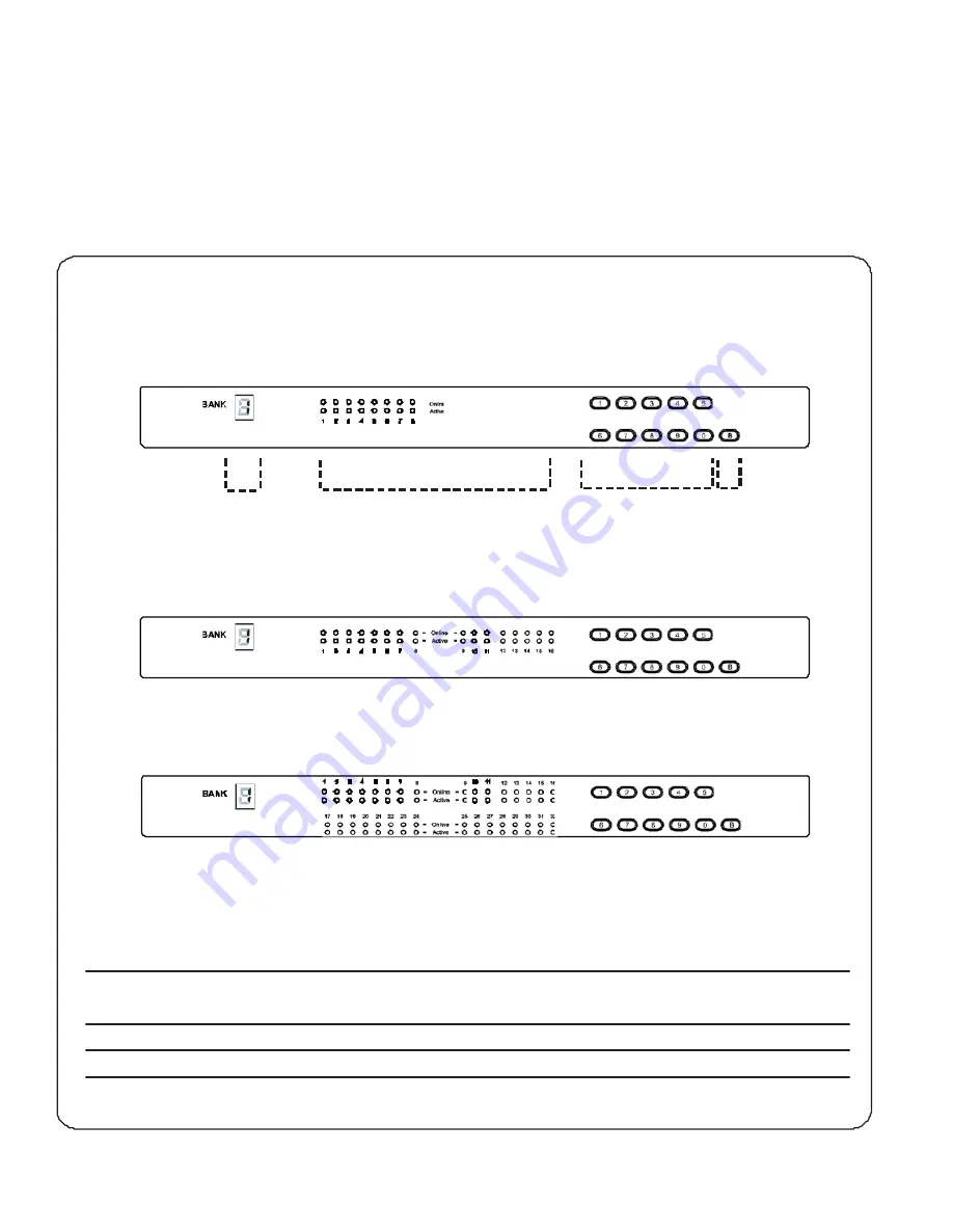
Front Panel - Port LED Indications

8 ports

Bank no.

PC port LEDs

Channel

button

Bank

button

16 ports

32 ports

Bank no.

7-Segment BANK LED indication

PC port LEDs

Online

:

Blue

LED on indicating a PC is connecting to the port

Active

:

Green

LED on indicating a selected channel

Channel button

Press to select channel from 01 to 32

Bank button

Select the bank from 1 to 8

Содержание KC101

Страница 1: ...on and productspecifications aresubject to changewithout notice For lastest product information pleasevisit Acnodes website atwww acnodes com 14628 Central Ave Chino CA91710 Tel 909 597 7588 Fax 909 597 1939 C opyright 2015 Acnodes C orp ...

Страница 2: ...open the chassis Opening it yourself could damage the equipment and invali date its warranty If any part of the equipment becomes damaged or stops functioning have it checked by qualified service personnel What the warranty does not cover Any product on which the serial number has been defaced modified or removed Damage deterioration or malfunction resulting from Accident misuse neglect fire water...

Страница 3: ...nection 1 3 IP Local console connection 1 4 IP console setting 1 5 KVM Cascade 1 6 IP Multi port connection to remote PDU 1 7 Specifications P 1 P 2 P 3 P 4 P 5 P 6 7 P 8 Part 2 Usage 2 1 KVM Button 2 2 Password 2 3 KVM OSD 2 4 KVM Hotkey Remote Console Hotkey 2 5 DC power 12V 24V 48V Input P 9 P 10 P 11 P 12 P 13 ...

Страница 4: ...at water moisture and vibration Unpacking The equipment comes with the standard parts shown in package content Check and make sure they are included and in good condition If anything is missing or damaged contact the supplier immediately Installation for standalone KVM Screw A 2 pcs Screw B 8 pcs M3 2 x 4 5 mm M4 x 10 mm Install each bracket using screws A B provided shown in Figure 1 Fix the KVM ...

Страница 5: ...onsole x 1 8 7 6 5 4 3 2 1 KCP1602 1 6 15 14 13 12 11 10 9 8 7 6 5 4 3 2 1 Cascade KCP3202 Local Console 32 31 30 29 28 27 26 25 16 15 14 13 12 11 10 9 24 23 22 21 20 19 18 17 8 7 6 5 4 3 2 1 Multi port for remote PDU CyberView IP KVM provides each RJ 45 Multi port to connect up to 16 pcs of InfraPower remote PDUs so the users can remotely control manage multi servers max 16 pcs remote PDU Flash U...

Страница 6: ...le max 40 meters VGA USB dongle USB VGA DVI USB dongle To connect DVI D connector to the computer s video card To connect USB connector to the computer s USB port VGA USB dongle To connect DB 15 connector to the computer s video card To connect USB connector to the computer s USB port VGA PS 2 dongle To connect DB 15 connector to the computer s video card To connect PS 2 keyboard connector to the ...

Страница 7: ...3 IP Local console connection Combo Cat6 IP KVM Local USB console 32 31 30 29 28 27 26 25 16 15 14 13 12 11 10 9 24 2 3 22 21 20 19 18 17 8 7 6 5 4 3 2 1 CAT 5 6 cable max 100m Network device hub or router ...

Страница 8: ...r 6 Enter Super user password The default is pass 7 Enter the new super user password 8 Re enter the new password 9 Change the desired IP address Subnet mask Gateway then click Setup Device to confirm the setting to IP KVM 10 The default address is as below The single IP KVM model such as KCP3202 http 192 168 1 22 11 Open Internet Explorer I E version 6 0 or above 12 Enter the IP KVM address into ...

Страница 9: ...e KVM level 2 To console VGA port 16 15 14 13 12 11 10 9 8 7 6 5 4 3 2 1 KC1601 Slave KVM level 3 16 15 14 13 12 11 10 9 8 7 6 5 4 3 2 1 KC1601 Slave KVM level 4 16 15 14 13 12 11 10 9 8 7 6 5 4 3 2 1 KC1601 Slave KVM level 5 16 15 14 13 12 11 10 9 8 7 6 5 4 3 2 1 KC 1601 Slave KVM 32 31 30 29 28 27 26 25 1 6 15 14 13 12 11 10 9 KC 3201 level 6 24 23 22 21 2 0 19 18 17 8 7 6 5 4 3 2 1 Slave KVM 32...

Страница 10: ...ly control and manage servers PDU together Combo IP KVM 32 31 30 29 28 27 2 6 2 5 16 15 14 1 3 12 11 10 9 2 4 23 22 21 20 19 1 8 1 7 8 7 6 5 4 3 2 1 Other band IP KVM can NOT connect InfraPower PDU Each RJ 45 Multi port connect max 16 pcs of InfraPower PDU To Multi port 1st level PDU 2nd level PDU 3rd level PDU To LINK port CAT 5 6 CAT 5 6 of the 1st PDU LINK OUT cable LINK OUT cable LINK OUT CUR ...

Страница 11: ... enter the IP KVM main page and select Remote Power Start Service Apply 1 PDU cascade port L INK O UT 2 Current display CURRENT A 225 ON OFF ON DIP 3 Dip switch O N D I P 1 2 3 4 5 6 7 8 4 Reset button RESET 1 2 3 4 5 6 7 8 For rackmount PDU 2 3 4 on the front panel left 1 on the rear panel ...

Страница 12: ...Expansion Up to 256 servers by 8 level cascade Compatibility Multi platform Mix PCs SUNs IBMs HPs DELLs Server Support Windows Vista 2003 XP 2000 Linux Netware Unix Power Input 100 or 240V AC at 50 or 60 Hz via IEC type cord OR AC DC power adapter 12V 3 3A optional Option DC 12V 24V 48V DC input Consumption Max 24 Watt Standby 5 Watt Regulatory Approval FCC CE Environmental Operating 0 to 50 C Sto...

Страница 13: ... KVM switch finally computer Front Panel Port LED Indications 8 ports Bank no PC port LEDs Channel button Bank button 16 ports 32 ports Bank no 7 Segment BANK LED indication PC port LEDs Online Blue LED on indicating a PC is connecting to the port Active Green LED on indicating a selected channel Channel button Press to select channel from 01 to 32 Bank button Select the bank from 1 to 8 ...

Страница 14: ...g without any change Remark a Blank has underscore while SPACE doesn t have b Press any alphanumeric key to move to next input item SPACE is treated as a valid character Change your password 1 Login the KVM in SUPERVISOR level by pressing your own user name password 2 Call KVM OSD menu by pressing the KVM hotkey Scroll Lock Scroll Lock Space Bar 3 Press F1 to the MAIN MENU 4 Select USER SECURITY 5...

Страница 15: ...previous or next port PgUp PgDn Switch to previous bank or next bank Display port 01 08 09 16 17 24 25 32 1 2 3 4 Remark Display port 17 32 for 32 port model only F1 Main Menu 01 LANGUAGE OSD language change 02 PORT NAME EDIT Define port name 03 PORT SEARCH Quick searching by port name 04 USER SECURITY Change password 05 ACCESS LIST Define user access authority 06 HOTKEY Change hotkey 07 TIME SETT...

Страница 16: ...o factory default Except User Security settings Scroll Lock Scroll Lock U Disable and enable password security Default security is ON To enable disable the screen saving Scroll Lock Scroll Lock L function and 10 minutes auto logout Default the screen saving is OFF Remarks Example of Scroll Lock Scroll Lock Bank no Port no Bank No 1 to 8 Port No 01 to 32 e g Bank 1 Port 4 Scroll Lock Scroll Lock 1 ...

Страница 17: ...t voltage 12 Volt 24 Volt 48 Volt Input range 9 18V 18 36V 36 75V Input current No load 50 mA 50 mA 50 mA Full load 4950 mA 2450 mA 1220 mA Output rating Output voltage 12 Volt 12 Volt 12 Volt Output current 4 16A 4 16A 4 16A Efficiency 84 85 85 Remarks Package does not include power cord ...

Отзывы: