


7.
CAUTION!
Guards must be installed when fan is within
reach of personnel or within eight (8) feet (2.5 m) of
working level or when deemed advisable for safety.
8. Remove the motor compartment cover (small hood).
CAUTION!
Before proceeding, make sure electrical
service to fan is locked in
“OFF”
position. Run wires
through the internal wiring post to the motor, to disconnect
switch if used.
WARNING!
The wiring post is sealed to the
curb cap with a large washer and sealing gasket. If the
wiring post is loosened, the seal may be broken, thereby
creating a possible water leak.
9. All wiring should be in accordance with local ordinances
and the National Electric Code.
FOR EC Motor Wiring
Go to pages 5 through 11 on how to wire and setup a EC
motor.
10.
WARNING!
Check voltage being supplied to the fan to
see that it corresponds with the motor nameplate voltage;
high or low voltage can seriously damage the motor. On
multi-voltage motors, check motor terminal connections to
make sure motor is internally connected for voltage being
supplied. Motor wiring diagram is located on the side of
the motor or in the motor wiring compartment for ECM
motors go to back of this form for wiring diagrams. Extra
care should be taken when wiring two speed motors since
improper connections will damage motor and void motor
warranty.
11. Apply power momentarily and compare the rotation of
the impeller with the directional arrow on fan.
WHEEL
ROTATION IS CLOCKWISE AS VIEWED FROM TOP
OF FAN.
WARNING!
Operation in the wrong direction
will deliver air but will overload the motor to the extent
of blowing fuses, overload protection and could seriously
damage the motor. In the case of single phase motors, the
reversing instructions will appear on the wiring diagram,
located either in the motor wiring compartment or on the
outside of the motor housing.
12. Using a minimum of eight (8) lag bolts - two (2) on
each side near corners, securely fasten fan to curb,
replace small hood and fasten all bolts securely. The
fan should rest on the curb as level as possible.
Over tightening the bolts can cause the inlet cap to distort
and push the inlet cone into the wheel.
MAINTENANCE
1. Under normal usage, no spare parts are recommended
for one year of operation. Recommended spare parts are
shown on page 4.
2.
CAUTION!
Before proceeding, make sure electrical
service to fan is locked in “OFF” position.
WINDMILLING:
Even when the power is locked out, fans
may cause injury or damage if the impeller is subject to
“windmilling” which is the turning of the impeller and drive
components due to a draft in the system. To guard against
this hazard, the impeller should be secured to physically
restrict rotational movement.
3. Motor bearings are pre-lubricated. Consult information
printed on the motor for lubrication instructions.
4. If motor requires replacement, one comparable to the
original with the same service factor and enclosure must
be used.
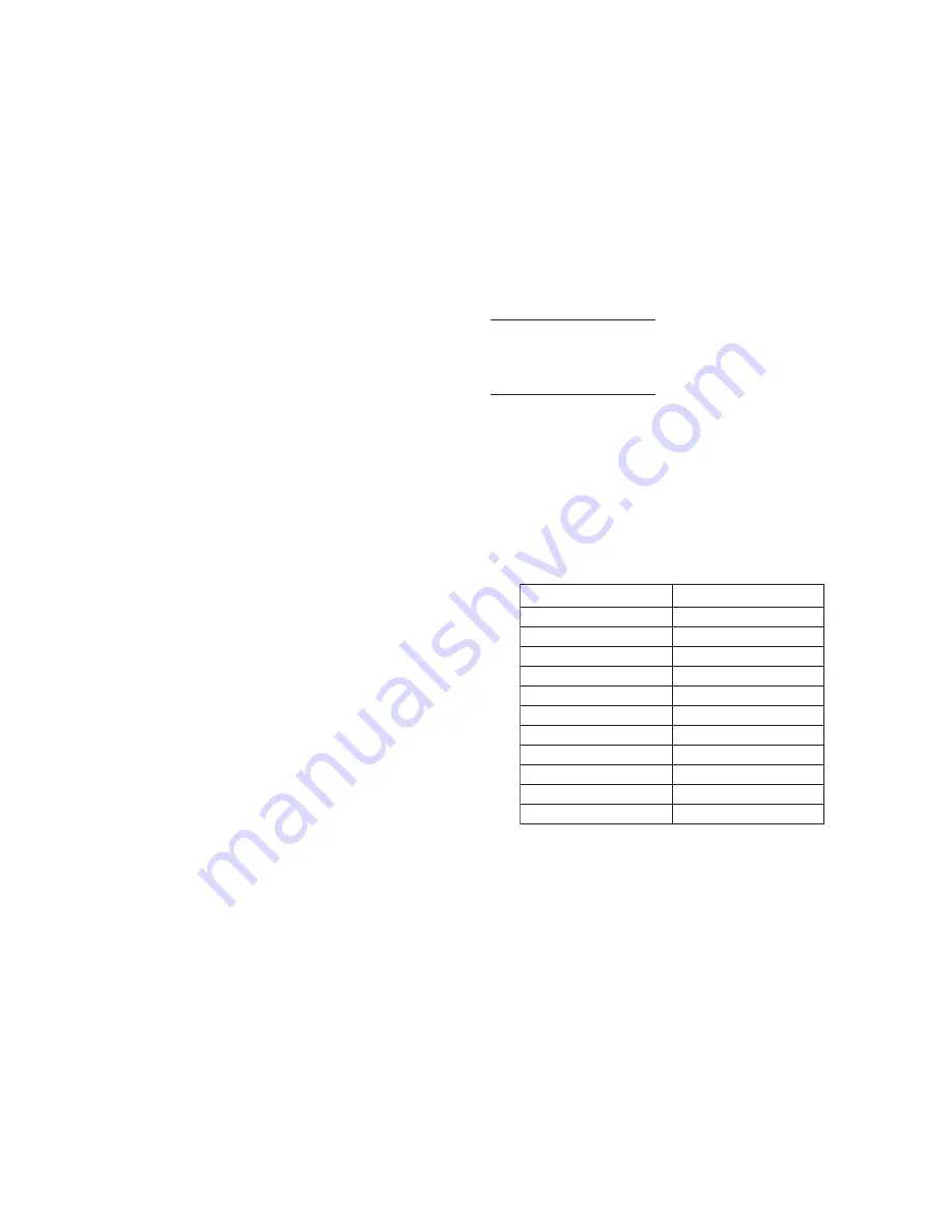
SET SCREW TIGHTENING SCHEDULE
1. Before initial operation of the fan, tighten set screws
according to the procedure outlined below.
2. After 500 operating hours or three months, whichever
comes first, tighten set screws to the full recommended
torque.
3. At least once a year, tighten set screws to the full
recommended torque.
PROCEDURE FOR TIGHTENING SET SCREWS IN
BEARINGS AND HUBS
One Set Screw Application
Using a torque wrench, tighten the set screw to the torque
recommended in Table 1.
Two Set Screw Application
1. Using a torque wrench, tighten one set screw to half of the
torque recommended in Table 1.
2. Tighten the second set screw to the full recommended
torque.
3. Tighten the first set screw to the full recommended torque.
VARIABLE FREQUENCY
DRIVES AND MOTOR
S
There are occasions when a Variable Frequency Drive (VFD)
will cause poor motor performance and possible damage.
To avoid these problems, the Company recommends the
following:
1. Select compatible motor and VFD inverter; if possible,
the motor and the inverter should be from the same
manufacturer or at least the inverter selected should be
recommended by the motor manufacturer.
2. A motor shaft grounding system should be used to prevent
motor bearing damage from eddy currents.
NOTE: The Company will not honor motor warranty claims
if the customer fails to follow these recommendations.
3
Set Screw Diameter
Torque (in-lbs)
#10
35
1/4
80
5/16
126
3/8
240
7/16
384
1/2
744
9/16
1080
5/8
1500
3/4
2580
7/8
3600
1
5400
Table 1. Recommended Tightening Torque
for Set Screws