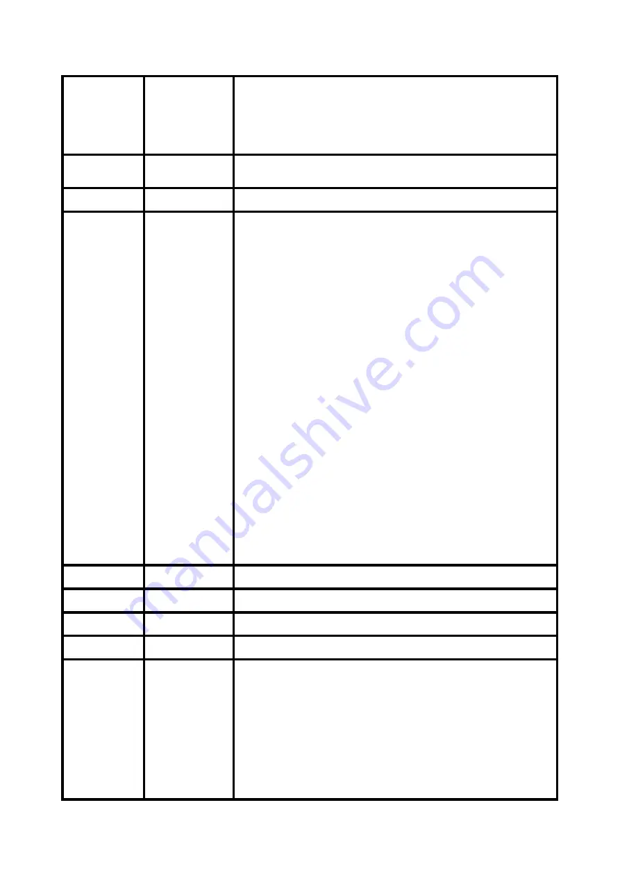
ACME GLAMOUR 700Z RGBY Скачать руководство пользователя страница 17


000-126 

127-199 

200-209 

210-255 

SPECIAL FUNCTIONS 

No function 

Focus compensate enable 

Reset 

No function 


000-255 

DIMMER 

0%

100% 

000-255 

DIMMER FINE 


000-019 

020-024 

025-064 

065-069 

070-084 

085-089 

090-104 

105-109 

110-124 

125-129 

130-144 

145-149 

150-164 

165-169 

170-184 

185-189 

190-204 

205-209 

210-224 

225-229 

230-244 

245-255 

SHUTTER 

Blackout 

Open 

Strobe 1: fast

slow 

Open 

Strobe 2: opening pulse, fast

slow 

Open 

Strobe 3: closing pulse, fast

slow 

Open 

Strobe 4: random strobe, fast

slow 

Open 

Strobe 5: random opening pulse, fast

slow 

Open 

Strobe 6: random closing pulse, fast

slow 

Open 

Strobe 7: burst pulse, fast

slow 

Open 

Strobe 8: random burst pulse, fast

slow 

Open 

Strobe 9: sine wave, fast

slow 

Open 

Strobe 10: burst, fast

slow 

Open 

10 

000-255 

RED (0%

100%) 

11 

000-255 

GREEN (0%

100%) 

12 

000-255 

BLUE (0%

100%) 

13 

000-255 

YELLOW (0%

100%) 

14 


000-009 

010-014 

015-019 

020-024 

025-029 

030-034 

035-039 

040-044 

COLOR MACRO 

Open 

Color1 

Color2 

Color3 

Color4 

Color5 

Color6 

Color7 


16E 

Содержание GLAMOUR 700Z RGBY

Страница 1: ......

Страница 2: ... 4 3 How To Set The Unit 5 3 1 Control Panel 5 3 2 Main Function 6 3 3 Home Position Adjustment 13 4 Control By Universal DMX Controller 14 4 1 DMX512 Connection 14 4 2 Address Setting 15 4 3 DMX512 Configuration 15 5 Troubleshooting 23 6 Fixture Cleaning 24 1E ...

Страница 3: ...ise the unit will be overheated Before operating ensure that the voltage and frequency of power supply match the power requirements of the unit It s important to ground the yellow green conductor to earth in order to avoid electric shock Minimum ambient temperature TA 0 Maximum ambient temperature TA 40 DO NOT connect the device to any dimmer pack During initial start up some smoke or smell may ar...

Страница 4: ...by unskilled people can lead to damage or malfunction Please contact the nearest authorized technical assistance center if needed Disconnect the mains power if the fixture is has not been used for a long time DO use the original packing materials before transporting it again DO NOT look directly at the light while the LED is on DO NOT start on the unit without LED enclosure or when housing is dama...

Страница 5: ... effect with variable speed Control DMX channel 15 27 17 channels Control Mode DMX512 RDM Firmware Upgrade Update via DMX link Construction Display LCD display Data In Out 3 pin 5 pin XLR Power In Out Power Connector in Protection Rating IP20 Features Electronic linear zoom system 3 rings control outstanding color macro effect Integrated powerful beam and wash features Dimension Weight 429 8 335 5...

Страница 6: ...LAY To show the various menus and the selected functions 2 Button MENU To enter into move backward or leave the menu DOWN To go forward in the selected functions UP To go backward in the selected functions ENTER To confirm the selected functions 5E ...

Страница 7: ...t circuit 7 POWER To connect to supply power 3 2 Main Function Turn on the unit press the MENU button into menu mode and press the UP DOWN button until the required function is shown on the monitor Select the function by the ENTER button Use the UP DOWN button to choose the submenu press the ENTER button to store and automatically return to the last menu Press the MENU button or let the unit idle ...

Страница 8: ...7E ...

Страница 9: ... the ENTER button to confirm Use the UP DOWN button to view the DMX channel values Press the MENU button back to the last menu or let the unit idle one minute to exit menu mode Fixture Settings Enter MENU mode select Fixture Settings press the ENTER button to confirm use the UP DOWN button to select Pan Invert Tilt Invert P T Feedback BL O P T Moving White Balance Cooling Mode Dimmer Curve or Dimm...

Страница 10: ...lue from 125 to 255 press the ENTER button to setup Press the MENU button back to the last menu or let the unit idle one minute to exit menu mode Cooling Mode To select Cooling Mode press the ENTER button to confirm Use the UP DOWN button to select Auto or Quiet Once selected press the ENTER button to setup Press the MENU button back to the last menu or let the unit idle one minute to exit menu mo...

Страница 11: ...cklight Intensity To select Backlight Intensity press the ENTER button to confirm Use the UP DOWN button to adjust the intensity from 1 dark to 10 bright Once selected press the ENTER button to setup and store Press the MENU button back to the last menu or let the unit idle one minute to exit menu mode Temperature Unit To Select Temperature Unit press the ENTER button to confirm Use the UP DOWN bu...

Страница 12: ...he ENTER button to confirm use the UP DOWN button to select Fixture Use Hour LED Use Hour Firmware Version or Error Logs Fixture Use Hour To select Fixture Use Hour press the ENTER button to confirm the fixture working hours will show on the display Press the MENU button to exit LED Use Hour To select LED Use Hour press the ENTER button to confirm use the UP DOWN button to select Total LED Hour LE...

Страница 13: ...he unit will run built in program to reset pan and tilt to their home positions press the ENTER button to store Press the MENU button to exit menu mode Effect To select Effect press the ENTER button to confirm Use the UP DOWN button to select No or Yes the unit will run built in program to reset effect to its home positions press the ENTER button to store Press the MENU button to exit menu mode Al...

Страница 14: ...D RESET option will be displayed When WARM RESET is selected the fixture will start a warm reset and exit when COLD RESET is selected 3 3 Home Position Adjustment Press the MENU button into menu mode then press the ENTER button for about 3 seconds into offset mode to adjust the home position Select the function by the ENTER button Use the UP DOWN button to choose the submenu press the ENTER button...

Страница 15: ...ate or damaged cables soldered joints or corroded connectors can easily distort the signal and shut down the system 3 The DMX output and input connectors are pass through to maintain the DMX circuit when one of the units power is disconnected 4 Each lighting unit needs to have a DMX address to receive the data by the controller The address number is between 0 511 usually 0 1 are equal to 1 5 The e...

Страница 16: ... the unit idle one minute to exit menu mode Please refer to the following diagram to address your DMX512 channel for the first 4 units Channel mode Unit 1 Address Unit 2 Address Unit 3 Address Unit 4 Address 15 channels 1 16 31 46 27 channels 1 28 55 82 17 channels 1 18 35 52 4 3 DMX512 Configuration Please refer to below configurations to control the fixtures Attentions 1 The unit will maintain t...

Страница 17: ... Strobe 2 opening pulse fast slow Open Strobe 3 closing pulse fast slow Open Strobe 4 random strobe fast slow Open Strobe 5 random opening pulse fast slow Open Strobe 6 random closing pulse fast slow Open Strobe 7 burst pulse fast slow Open Strobe 8 random burst pulse fast slow Open Strobe 9 sine wave fast slow Open Strobe 10 burst fast slow Open 10 000 255 RED 0 100 11 000 255 GREEN 0 100 12 000 ...

Страница 18: ...230 234 235 239 240 244 245 249 250 255 Color8 Color9 Color10 Color11 Color12 Color13 Color14 Color15 Color16 Color17 Color18 Color19 Color20 Color21 Color22 Color23 Color24 Color25 Color26 Color27 Color28 Color29 Color30 Color31 Color32 Color33 Open Color33 Color1 Stop Color1 Color33 Open Fast macro Medium macro Slow macro Open 15 000 255 ZOOM 60 10 27 Channels Mode CHANNEL VALUE FUNCTION 1 000 2...

Страница 19: ...4 185 189 190 204 205 209 210 224 225 229 230 244 245 255 SHUTTER Blackout Open Strobe 1 fast slow Open Strobe 2 opening pulse fast slow Open Strobe 3 closing pulse fast slow Open Strobe 4 random strobe fast slow Open Strobe 5 random opening pulse fast slow Open Strobe 6 random closing pulse fast slow Open Strobe 7 burst pulse fast slow Open Strobe 8 random burst pulse fast slow Open Strobe 9 sine...

Страница 20: ...en Color1 Color2 Color3 Color4 Color5 Color6 Color7 Color8 Color9 Color10 Color11 Color12 Color13 Color14 Color15 Color16 Color17 Color18 Color19 Color20 Color21 Color22 Color23 Color24 Color25 Color26 Color27 Color28 Color29 Color30 Color31 Color32 Color33 16 000 255 RED 2 0 100 17 000 255 GREEN 2 0 100 18 000 255 BLUE 2 0 100 19 000 255 YELLOW 2 0 100 20 000 255 COLOR 2 The same as CH15 COLOR 1 ...

Страница 21: ...ct3 Effect4 Effect5 Effect6 Effect7 Effect8 Effect9 Effect10 Effect11 Effect12 Effect13 Effect14 Effect15 Effect16 Effect17 27 000 255 COLOR MACRO SPEED slow fast 17 Channels Mode CHANNEL VALUE FUNCTION 1 000 255 PAN 0 540 2 000 255 PAN FINE 3 000 255 TILT 0 220 4 000 255 TILT FINE 5 000 255 PAN TILT SPEED fast slow 6 000 126 127 199 200 209 210 255 SPECIAL FUNCTIONS No function Focus compensate e...

Страница 22: ...be 5 random opening pulse fast slow Open Strobe 6 random closing pulse fast slow Open Strobe 7 burst pulse fast slow Open Strobe 8 random burst pulse fast slow Open Strobe 9 sine wave fast slow Open Strobe 10 burst fast slow Open 10 000 255 RED 0 100 11 000 255 GREEN 0 100 12 000 255 BLUE 0 100 13 000 255 YELLOW 0 100 14 000 009 010 014 015 019 020 024 025 029 030 034 035 039 040 044 045 049 050 0...

Страница 23: ...r21 Color22 Color23 Color24 Color25 Color26 Color27 Color28 Color29 Color30 Color31 Color32 Color33 Open Color33 Color1 Stop Color1 Color33 Open Fast macro Medium macro Slow macro Open 15 000 255 ZOOM 60 10 16 000 007 008 016 017 025 026 034 035 043 044 052 053 061 062 070 071 079 080 088 089 097 098 106 107 115 116 124 125 133 134 142 EFFECT OFF Effect1 Effect2 Effect3 Effect4 Effect5 Effect6 Eff...

Страница 24: ...3 Check the power on LED to see if it can be light up or not B Not responding to DMX controller 1 DMX LED should be on If not check DMX connectors cables to see if they are linked properly 2 If the DMX LED is on and no response to the channel check the address settings and DMX polarity 3 If you have intermittent DMX signal problems check the pins on connectors or on PCB of the unit or the previous...

Страница 25: ...ency depends on the environment in which the fixture operates damp smoky or particularly dirty surrounding can cause greater accumulation of dirt on the unit s optics Clean with soft cloth and use normal glass to clean liquid Always dry the parts carefully Clean the external optics at least every 20 days Clean the internal optics at least every 30 60 days 24E ...

Страница 26: ...25E ...

Страница 27: ...26E ...

Страница 28: ...Innovation Quality Performance ...

Отзывы: