Chapter 3
94
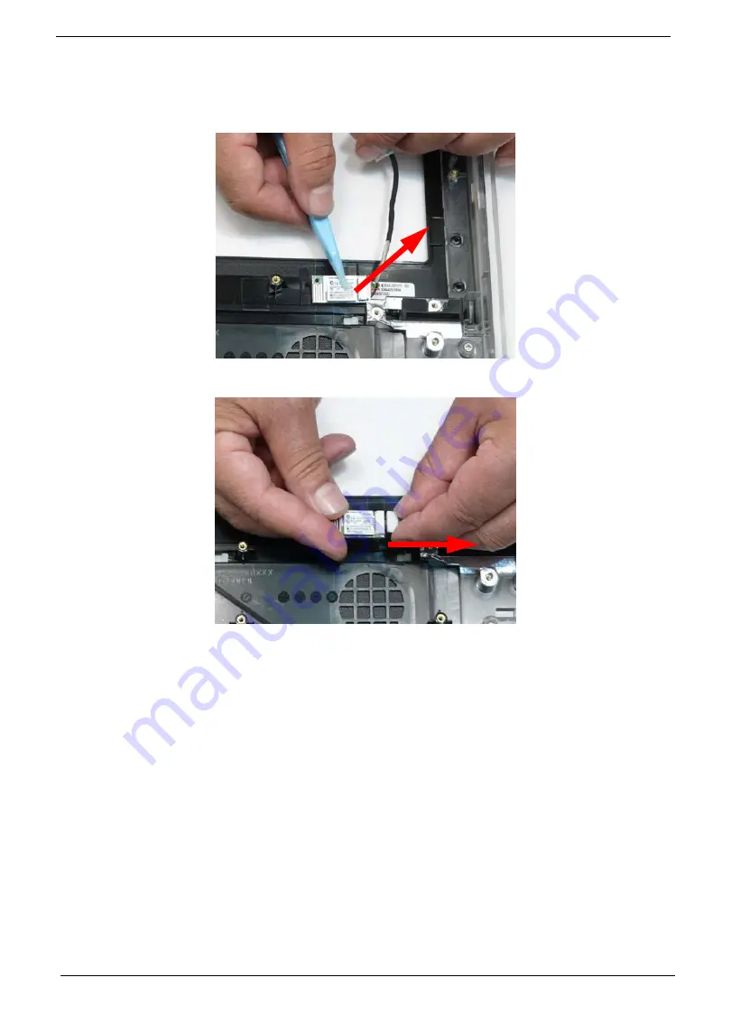
Removing the Bluetooth Module
1.
See “Removing the Speakers” on page 92.
2.
Pry the Bluetooth module off the adhesive.
3.
Disconnect the Bluetooth cable.
Содержание ZX4800 Series
Страница 6: ...VI Laptopblue ...
Страница 10: ...X Table of Contents Laptopblue ...
Страница 47: ...Chapter 2 37 Laptopblue ...
Страница 53: ...43 Chapter 3 4 Lift the ODD bezel away 5 Close the ODD assembly Laptopblue ...
Страница 57: ...47 Chapter 3 5 Forcefully pry the rear cover from the assembly i ii iii iv Laptopblue ...
Страница 59: ...49 Chapter 3 4 Disconnect the audio cable from the audio board Laptopblue ...
Страница 62: ...Chapter 3 52 7 Remove the HDD module from the bracket Laptopblue ...
Страница 74: ...Chapter 3 64 15 Lift the mainboard shielding away from the chassis Laptopblue ...
Страница 76: ...Chapter 3 66 4 Lift the WLAN module away Laptopblue ...
Страница 78: ...Chapter 3 68 4 Lift the TV module away 5 Disconnect the other end of the TV cable and remove Laptopblue ...
Страница 82: ...Chapter 3 72 4 Remove the fan Laptopblue ...
Страница 87: ...77 Chapter 3 4 Remove the cables from the guide clips Laptopblue ...
Страница 91: ...81 Chapter 3 8 Remove the LVDS cable 9 Remove the adhesive tape off the sensor cables Laptopblue ...
Страница 97: ...87 Chapter 3 4 Lift the power board away from the bezel Laptopblue ...
Страница 100: ...Chapter 3 90 4 Disconnect the webcam cable Laptopblue ...
Страница 107: ...97 Chapter 3 3 Replace the speaker cable into the retention guides 4 Replace the speaker cable adhesive tape Laptopblue ...
Страница 110: ...Chapter 3 100 Replacing the Webcam 1 Connect the webcam cable to the webcam board 2 Replace the webcam Laptopblue ...
Страница 111: ...101 Chapter 3 3 Replace the two 2 screws Step Size Quantity Screw Type Webcam M2 3 2 Laptopblue ...
Страница 115: ...105 Chapter 3 3 Replace the four 4 screws Step Size Quantity Screw Type LCD Panel M3 4 4 Laptopblue ...
Страница 120: ...Chapter 3 110 12 Adhere the tape over the sensor cables and lay the cable through the retention hook Laptopblue ...
Страница 121: ...111 Chapter 3 13 Connect the LVDS cable 14 Adhere the LVDC cable protective cover Laptopblue ...
Страница 122: ...Chapter 3 112 15 Lay the LVDS cable through the retention guides and into the guide clip Laptopblue ...
Страница 125: ...115 Chapter 3 3 Replace the two 2 screws Step Size Quantity Screw Type USB Board M2 5 4 2 Laptopblue ...
Страница 128: ...Chapter 3 118 Replacing the Thermal Module 1 Replace the thermal module 2 Tighten the three 3 captive screws Laptopblue ...
Страница 131: ...121 Chapter 3 Replacing the DIMM Module 1 Replace the DIMM Module 2 Press down to lock into place Laptopblue ...
Страница 134: ...Chapter 3 124 3 Replace the two 2 connectors The gray cable is placed closest to the fan Laptopblue ...
Страница 138: ...Chapter 3 128 4 Connect the left and right touchscreen sensor cable connectors Laptopblue ...
Страница 140: ...Chapter 3 130 4 Adhere the inverter cable tape 5 Connect the webcam cable 6 Connect the LVDS cable Laptopblue ...
Страница 143: ...133 Chapter 3 4 Connect the two 2 LCD to inverter board cables 1 and 2 1 2 Laptopblue ...
Страница 146: ...Chapter 3 136 7 Replace the two 2 screws Step Size Quantity Screw Type ODD Module M2 5 4 2 Laptopblue ...
Страница 151: ...141 Chapter 3 4 Replace 4 four screws Step Size Quantity Screw Type Rear Cover M2 5 7 4 Laptopblue ...
Страница 155: ...145 Chapter 3 4 Close the ODD Laptopblue ...
Страница 193: ...183 Appendix B Laptopblue ...
Страница 196: ...186 Laptopblue ...
Страница 197: ...187 Laptopblue ...
Страница 198: ...188 Laptopblue ...


