32
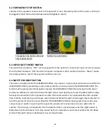
6.2 EMERGENCY STOP BUTTON
Located on the operators console next to the operators screen. Depressing the button causes an E-stop to
be triggered. Twist the button clockwise and pull slightly to reset it.
Emergency Stop Button & Keyed
Safety Pre-reset Button
Safety Reset Switch
6.3 KEYED SAFETY RESET SWITCH
This switch has 3 positions. “OFF” removes power from the operator’s console but does not remove power
from the Main Enclosure. “ON” boots the computer and powers other machine functions. “Reset” causes
the safety system to reset if the required conditions are met.
6.4 SAFETY PRE-RESET BUTTON
This button is located inside the HAZARDOUS ZONE. Its purpose is to protect personnel who are within the
HAZARDOUS ZONE by preventing a system safety reset by someone outside the HAZARDOUS ZONE. The
button must be pressed by the last person leaving the HAZARDOUS ZONE. After pressing the Pre-Reset
button you will have 12 seconds to break the light curtain upon leaving and reset the safety system using
the keyed reset switch on the operator’s console. If the reset switch is not operated within the required
time it will be necessary to push the pre-reset button and break the Light Curtain again. Never attempt to
reset the system if someone else is still within the HAZARDOUS ZONE as moving machinery could cause
serious injury or death. You will need to repeat the procedure if a reset does not occur within the 12
seconds. This timing is not adjustable. The Pre-Reset button is only necessary when the Light Curtain or
Brake Beam has been broken. An E-stop caused by the E-stop button can be reset without the Pre-Reset
button if the Light Curtain or Brake Beam has not been broken.
Содержание Wood Runner
Страница 5: ...5 ...
Страница 36: ...36 ...
Страница 37: ...37 ...
Страница 54: ...54 ...
Страница 55: ...55 10 DETAILED PARTS IDENTIFICATION WOOD RUNNER 10 1 RUNWAY ASSEMBLY ...
Страница 58: ...58 10 3 RUNWAY DRIVE ASSEMBLY ...
Страница 61: ...61 10 5 GANTRY ASSEMBLY ...
Страница 62: ...62 GANTRY ASSEMBLY ...
Страница 64: ...64 10 6 PICKING HEAD ASSEMBLY ...
Страница 65: ...65 PICKING HEAD ASSEMBLY ...
Страница 68: ...68 10 7 ELECTRICAL PANEL ASSEMBLY ...
Страница 70: ...70 10 8 GANTRY ENCLOSURE ASSEMBLY ...
Страница 72: ...72 10 9 CONSOLE ASSEMBLY ...
Страница 73: ...73 CONSOLE ASSEMBLY ...
Страница 75: ...75 10 10 AIR SUPPLY ASSEMBLY ...
Страница 77: ...77 10 11 GANTRY VALVE ASSEMBLY ...
Страница 79: ...79 10 12 GANTRY BRAKE ASSEMBLY ...
Страница 81: ...81 11 ELECTRICAL DIAGRAMS 11 1 SYSTEM OVERVIEW ...
Страница 82: ...82 11 2 MAIN ENCLOSURE LOW VOLTAGE ...
Страница 83: ...83 11 3 GANTRY WIRING LOW VOLTAGE ...
Страница 84: ...84 11 4 I O CHART ...
Страница 85: ...85 11 5 INFEED WIRING LOW VOLTAGE ...
Страница 86: ...86 11 6 OPERATORS CONSOLE ...
Страница 87: ...87 11 7 MAIN ENCLOSURE HIGH VOLTAGE ...
Страница 88: ...88 11 8 MAIN ENCLOSURE RECEPTACLE WIRING ...
Страница 89: ...89 11 9 SAFETY CIRCUIT LAYOUT ...
Страница 90: ...90 11 10 SAFETY CIRCUIT DIAGRAM ...
Страница 91: ...91 11 11 BRAKE SENSOR DIAGNOSIS ...
Страница 92: ...92 12 PNEUMATIC DIAGRAMS 12 1 SINGLE HEAD GANTRY ...
Страница 93: ...93 12 2 DOUBLE HEAD GANTRY ...
Страница 94: ...94 12 3 INFEED DECK ...

