25
5 OPERATING INSTRUCTIONS
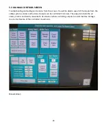
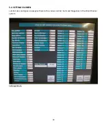
You will need to familiarize yourself with the different screens available on the Wood Runner computer.
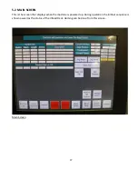
Navigation to the various screens is selected by buttons on the Main screen.
5.1 MACHINE STARTUP
Check to see that you have completed all of the connections properly as outlined above and make
sure all personnel are clear of the
Hazardous Zone
. See Safe Operating Procedures section earlier
in manual.
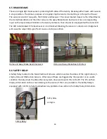
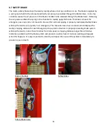
Check to see that Gantry Brake has been released as described in Section 4.
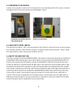
Depress the E-stop button on the Operator Console to insure that the machine does not start.
Turn the Main Disconnect to the ON position.
Turn the safety lockout valve to the ON position. This is located on the Air Supply Assembly. Check
the main pressure gauge for proper 90 psi pressure setting and adjust the regulator if necessary.
Turn the key switch on the Operators Console to the ON position and wait for the Computer to
display the Main screen.
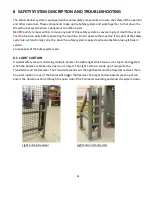
Adjust the Light Curtain alignment as covered in section 8.6 of this manual. A Light Curtain that is
not aligned properly will prevent the safety system from resetting and the machine from operating.
Enter the Hazardous zone and press the Pre-Reset button. You will now have 8 seconds to break
the Light Curtain beam and reset the system using the reset key switch. See section 6.4 for a
description of the Pre-Reset Button operation.
Turn the key switch to the Reset position momentarily and the Enable screen should be shown. If a
Reset does not occur recheck the Light Curtain and Brake Beam adjustment. Refer to section 6 on
the Safety system.
Read and follow the instructions on the Enable Screen and then touch the Enable button. Enabling
the system will put the machine in operational mode. This should power up the servomotor for the
Gantry and energize the air system. The Picking Head and Screw Motor cylinders will retract to
their upper position. The Enable screen will change to the Main screen if the machine successfully
enables. See the Troubleshooting Section if the enable fails.
Содержание Wood Runner
Страница 5: ...5 ...
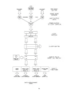
Страница 36: ...36 ...
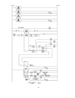
Страница 37: ...37 ...
Страница 54: ...54 ...
Страница 55: ...55 10 DETAILED PARTS IDENTIFICATION WOOD RUNNER 10 1 RUNWAY ASSEMBLY ...
Страница 58: ...58 10 3 RUNWAY DRIVE ASSEMBLY ...
Страница 61: ...61 10 5 GANTRY ASSEMBLY ...
Страница 62: ...62 GANTRY ASSEMBLY ...
Страница 64: ...64 10 6 PICKING HEAD ASSEMBLY ...
Страница 65: ...65 PICKING HEAD ASSEMBLY ...
Страница 68: ...68 10 7 ELECTRICAL PANEL ASSEMBLY ...
Страница 70: ...70 10 8 GANTRY ENCLOSURE ASSEMBLY ...
Страница 72: ...72 10 9 CONSOLE ASSEMBLY ...
Страница 73: ...73 CONSOLE ASSEMBLY ...
Страница 75: ...75 10 10 AIR SUPPLY ASSEMBLY ...
Страница 77: ...77 10 11 GANTRY VALVE ASSEMBLY ...
Страница 79: ...79 10 12 GANTRY BRAKE ASSEMBLY ...
Страница 81: ...81 11 ELECTRICAL DIAGRAMS 11 1 SYSTEM OVERVIEW ...
Страница 82: ...82 11 2 MAIN ENCLOSURE LOW VOLTAGE ...
Страница 83: ...83 11 3 GANTRY WIRING LOW VOLTAGE ...
Страница 84: ...84 11 4 I O CHART ...
Страница 85: ...85 11 5 INFEED WIRING LOW VOLTAGE ...
Страница 86: ...86 11 6 OPERATORS CONSOLE ...
Страница 87: ...87 11 7 MAIN ENCLOSURE HIGH VOLTAGE ...
Страница 88: ...88 11 8 MAIN ENCLOSURE RECEPTACLE WIRING ...
Страница 89: ...89 11 9 SAFETY CIRCUIT LAYOUT ...
Страница 90: ...90 11 10 SAFETY CIRCUIT DIAGRAM ...
Страница 91: ...91 11 11 BRAKE SENSOR DIAGNOSIS ...
Страница 92: ...92 12 PNEUMATIC DIAGRAMS 12 1 SINGLE HEAD GANTRY ...
Страница 93: ...93 12 2 DOUBLE HEAD GANTRY ...
Страница 94: ...94 12 3 INFEED DECK ...


