background image

Chapter 6

112

ODD PLDS BD COMBO HH DL 12X DH-12E3SH 
LF+HF Black Bezel SATA (HF+Win7)

KO.0120F.001

ODD HLDS BD RW HH 8X BH38N Black Bezel 
SATA HF +Win7 

KU.0080D.061

ODD PLDS BD RW HH DL 8X DH-8B2SH LF+HF 
Black Bezel SATA (Win7+HF) 

KU.0080F.018

ODD HLDS Super-Multi DRIVE HH 16X GH70N 
LF+HF Black Bezel SATA (Win7)

KU.0160D.055

ODD PLDS Super-Multi DRIVE HH DL 16X DH-
16ABSH LF Black Bezel (HF+Win7) SATA 

KU.0160F.011

ODD PIONEER Super-Multi DRIVE HH DL 16X 
DVR-219RS LF Black Bezel SATA (Win7+HF)

KU.01605.007

ODD HLDS BD COMBO HH 12X CH29N Black 
Bezel SATA HF + Win7 

KO.0120D.001

ODD PLDS BD COMBO HH DL 12X DH-12E3SH 
LF+HF Black Bezel SATA (HF+Win7)

KO.0120F.001

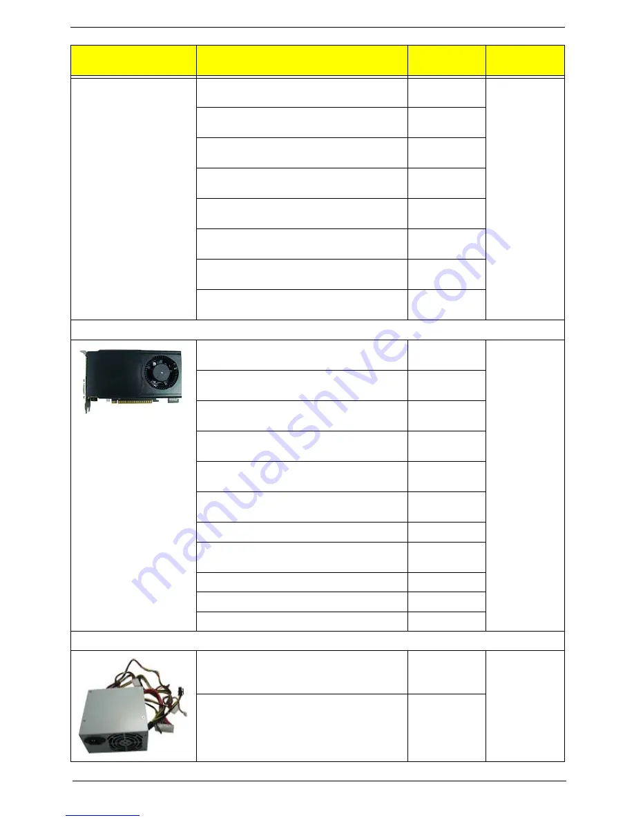
VGA

288-5N194-000AC GTX550Ti 1GB 192bit GDDR5 
DVI + DVI + HDMI + DP SAMSUNG ATX 

VG.PCPT5.501

N/A

288-6N178-000AC GT545 3GB 192bit DDR3 DVI 
+ HDMI + DP SAMSUNG ATX

VG.PCP54.5A1

288-6N178-100AC GT545 3GB 192bit DDR3 DVI 
+ HDMI + DP HYNIX ATX 

VG.PCP54.5A2

288-1N222-001AC 510 1GB DDR3 64bits DVII + 
HDMI + VGA Hynix ATX

VG.PCPT5.101

288-1E181-101AC HD6570 1GB DDR3 128bits 
DVI-I (DL) + HDMI SAMSUNG ATX

VG.APC65.711

288-2E180-000AC HD6450 1GB SDDR3 64bits 
DVI-I + HDMI SAMSUNG (ATX)

VG.APC64.522

GTX660 2GB GDDR5 DVI DVI HDMI DP ATX

VG.PCP66.001

AMD HD7870 2GB GDDR5 DVI HDMI miniDP 
miniDP ATX BRACKET ROHS

VG.A7870.001

GTX645 1GB GDDR5 DVI DVI HDMI DP ATX

VG.PCP64.501

GT635 3GB 192bit DDR3 DVI HDMI DP ATX

VG.PCP63.501

GT630 2GB 128bit DDR3 DVI HDMI VGA ATX 

VG.PCP63.001

Power Supply

FSP500-70EP 500W Active PFC 100-127V/220-
240V, full 500W

PY.50008.007

32

PS-6451-5AE

PY.5000B.003

Category

Part Number

Acer P/N

Exploded 

Diagram Item


Содержание Predator G3620

Страница 1: ...Acer Predator G3620 Service Guide PRINTED IN TAIWAN ...

Страница 2: ...ii Revision History Please refer to the table below for the updates made on this service guide Date Chapter Updates ...

Страница 3: ...ublication may be reproduced transmitted transcribed stored in a retrieval system or translated into any language or computer language in any form or by any means electronic mechanical magnetic optical chemical manual or otherwise without the prior written permission of Acer Incorporated ...

Страница 4: ... programs prove defective following their purchase the buyer and not Acer Incorporated its distributor or its dealer assumes the entire cost of all necessary servicing repair and any incidental or consequential damages resulting from any defect in the software Acer is a registered trademark of Acer Corporation Intel is a registered trademark of Intel Corporation Pentium Dual Core Celeron Dual Core...

Страница 5: ...ditional information related to the current topic WARNING Alerts you to any physical risk or system damage that might result from doing or not doing specific actions CAUTION Gives precautionary measures to avoid possible hardware or software problems IMPORTANT Reminds you to do specific actions relevant to the accomplishment of procedures ...

Страница 6: ...h cases please contact your regional offices or the responsible personnel channel to provide you with further technical details FRU Information Please note WHEN ORDERING FRU PARTS that you should check the most up to date information available on your regional web or channel If for whatever reason a part number change is made it will not be noted in the printed Service Guide For ACER AUTHORIZED SE...

Страница 7: ...ing the Hard Disk Drive 38 Removing the Bracket of Removable HDD 41 Removing the Optical Drive 42 Removing the System Fan 44 Removing the Power Supply 46 Removing the Mainboard 48 Removing the Top Cover 51 Removing the Top USB and Audio I O Assembly 53 Removing the Card Reader 54 Assembly Requirements 55 Assembly Procedure 56 Romoving the Side Panel 57 Removing the Cage of Hard Disk Drive 58 Remov...

Страница 8: ... System Check Procedures 85 Power System Check 85 System External Inspection 85 System Internal Inspection 85 Beep Codes 86 Checkpoints 87 BIOS Recovery 90 Jumper and Connector Information 93 M B Placement 93 Jumper Setting 95 Internal header pin definition 98 Connector pin definition 101 FRU Field Replaceable Unit List 106 Predator G3620 Exploded Diagram 107 Predator G3620 FRU List 109 ...

Страница 9: ...pe LGA1155 FMB 65W 95W and support K sku OC need support 130w power design Chipset PCH Intel B75 PCB uATX max 4 Layers Memory subsystem 2 channels 2 DIMMs per channel Different colors for DIMM 0 and DIMM 1 Dual channel should be enabled always when plug in 2 same memory size DDRIII memory module DDR3 4 Max memory of 16 GB supported using 4Gb tech Support DDR3 1 5V 1333 1600 1GB 2GB 4GB Graphics In...

Страница 10: ...VGA card we may have double width card support Audio Realtek ALC662VD Rear IO 3 jack Front IO 1 Microphone in 1 head phone jack Serial ATA controller SATA 6 different color to identify SATA 6Gb s and SATA 3Gb s 1 SATA 6 Gb s and 5 SATA 3Gb s HDD AHCI Native IDE is required ODD Support BD SuperMulti DVD ROM LAN Giga Lan Intel 82579V co lay with Realtek LAN 8111E SUPER IO Support PECI 3 0 and detect...

Страница 11: ... stack 1 3 ports Audio jack 1 COM port for China only option On board connectors 1 ILM Independent Loading Mechanism for LGA 1155 CPU assign by Acer 1 24 pin ATX PWR connector 1 H2X4 Power Supply Connector 4 DDR3 DIMM Socket 5 SATA 3Gb s 1 SATA 6Gb s 2 USB2 0 H5X2 Header support 4 ports 1 USB 3 0 H10x2 Header support 2 ports Location is defined in EE requirement 1 Front Audio Pannel H5X2 header 1 ...

Страница 12: ...4 Chapter 1 System BIOS Type Use SPI Flash System BIOS 8MB Kernel AMI Kernel with Acer skin Power supply Non PFC 300W PFC 300W FR 300W Support models are listed on AVLC ...

Страница 13: ...Chapter 1 5 Block Diagram ...

Страница 14: ...ptical drive button 2 Power button 9 Master optical drive button 3 XD XD Picture slot 10 MS MS PRO slot 4 CF I II CompactFlash Type I II slot 11 SD MMC Secure Digital MultiMedia Card slot 5 Master optical drive 12 Micro SD slot 6 Slave optical drive 13 Microphone in jack 7 Removable HDD bay Removable HDD bay for XXX bezel 14 Headphone Speaker out line out jack ...

Страница 15: ...wer connector 2 PS2 keyboard port 3 HDMI port 4 VGA port 5 USB 2 0 ports 6 Line out jack 7 Microphone in jack 8 Expansion slot Modem card and Graphics card 9 line in jack 10 RJ45 LAN connector 11 USB 3 0 ports 12 System FAN 13 PS2 mouse port ...

Страница 16: ... version P01 A0 BIOS ROM type SPI Flash BIOS ROM size 8Mb Support protocol SMBIOS DMI 2 4 DMI2 0 Device Boot Support 1st priority SATA HDD 2nd priority CD ROM 3rd priority Removable Device 4th priority LAN 5th priority USB device Support to LS 120 drive YES Support to BIOS boot block feature YES Hotkey Function Description Del Enter BIOS Setup Utility Press while the system is booting to enter BIO...

Страница 17: ...pin DDRIII Support to parity check feature Yes Support to error correction code ECC feature No Memory module combinations You can install memory modules in any combination as long as they match the above specifications Item Specification SATA controller Intel B75 Number of SATA channel SATA X 6 1 SATA 6 Gb s and 5 SATA 3Gb s Support mode HDD AHCI Native IDE is required ODD Support BD SuperMulti DV...

Страница 18: ...ly integrated audio solutions for multimedia PCs and ultra mobile devices Two stereo ADCs and one stereo digital microphone converter are integrated and can support a microphone array with Acoustic Echo Cancellation AEC Beam Forming BF and Noise Suppression NS technologies with EAX Direct Sound 3D I3DL2 compatibility Music synthesizer No Sampling rate 192kHz max MPU 401 UART support No Microphone ...

Страница 19: ...d be less than Devices wake up from S5 should be less than 10 seconds Devices S1 S3 S4 S5 Power Button V V V V USB Keyboard Mouse V V N A N A PME Disabled Disabled Disabled Disabled RCT Disabled Disabled Disabled Disabled WOR Disabled Disabled Disabled Disabled ...

Страница 20: ...external switch Button modem ring in keyboard an mouse for APM mode Resume recovery time 7 10sec Suspend Mode Independent power management timer 2 120minutes time step 10minute or pushing extern switch button CPU goes into SMM CPU asserts STPCLK and goes into the Stop Grant State LED on panel turns amber colour Hard disk drive goes into SLEEP mode for ATA standard interface Disable H sync and V sy...

Страница 21: ...rompted Run Setup message to make changes to the CMOS setup NOTE If you repeatedly receive Run Setup messages the battery may be bad In this case the system cannot retain configuration values in CMOS Ask a qualified technician for assistance CMOS setup loads the configuration values in a battery backed nonvolatile memory called CMOS RAM This memory area is not part of the system RAM which allows c...

Страница 22: ...page of a multiple page menu Home Move the cursor to the first page of a multiple page menu End Move the cursor to the last page of a multiple page menu and keys Select a value for the currently selected field only if it is user configurable Press these keys repeatedly to display each possible entry or the Enter key to choose from a pop up menu NOTE Grayed out fields are not user configurable Ente...

Страница 23: ...te when the BIOS setup utility was built Processor Type of CPU installed on the system Core Frequency Core speed of the CPU installed on the system Count Physical CPU count Memory Size Total size of system memory installed on the system Product Name Product name of the system System Serial Number Serial number of the system Asset Tag Number Asset tag number of this system System Date Set the date ...

Страница 24: ...ccess the Miscellaneous submenu Advanced Chipset Configuration Press Enter to access the Advanced Chipset Configuration submenu Integrated Peripherals Press Enter to access the Integrated Peripherals submenu PC Health Status Press Enter to access the PC Health Status submenu ...

Страница 25: ...HCI Port0 1 2 3 4 5 Displays the status of auto detection of the AHCI device Bootup Num lock Selects power on state for Num Lock On Off USB Beep Message Enables or disables BIOS to display error beeps or messages during USB device enumeration Enabled Disabled ...

Страница 26: ...m attempts to insert a code in the buffer preventing damage and worm propagation When disabled the processor forces the Execute Disable XD Bit feature flag to always return to 0 Enabled Disabled Intel VT Enables or disables the Virtualization Technology VT availability If enabled a virtual machine manager VMM can utilize the additional hardware virtualization capabilities provided by this technolo...

Страница 27: ...for legacy USB devices Enabled Disabled USB Storage Emulation If Auto USB device equal or less than 2GB will be emulated as Floppy and remaining as harddrive Forced FDD option can be used to force a HDD formatted drive to boot as FDD Ex ZIP drive Auto Floppy Hard Disk Onboard Audio Controller Enables or disables the onboard audio controller Enabled Disabled Onboard LAN Controller Enables or disabl...

Страница 28: ...20 Chapter 2 PC Health Status Parameter Description Option Smart Fan Enables or disables the smart system fan control function Enabled Disabled ...

Страница 29: ...PCIE LAN card You must use an ATX power supply in order to use this feature Use this item to dowake up action if inserting the PCIE card Enabled Disabled Power On by Onboard LAN Enables or disables an onboard LAN controller to generate a wake event Enabled Disabled Wake Up by PS 2 KB Mouse Enables or disables to wake up the system from a power saving mode using a PS2 keyboard or mouse Enabled Disa...

Страница 30: ...rd then press Enter 4 Retype the password to verify the first entry then press Enter again 5 Press F10 6 Select Yes to save the new password and close the Setup Utility Removing a supervisor password 1 Use the up down arrow keys to select Change Supervisor Password menu then press Enter 2 Enter the current password then press Enter 3 Press Enter twice without entering anything in the password fiel...

Страница 31: ...ess the Optical Disk Drive Priority submenu and specify the boot device priority sequence from available optical drives Removable Device Priority Press Enter to access the Removable Device Priority submenu and specify the boot device priority sequence from available removable drives Network Device Priority Press Enter to access the Network Device Priority submenu and specify the boot device priori...

Страница 32: ...nu and press Enter Save Changes Select this option and press Enter to save all the changes and return to the BIOS Setup Utility Discard Changes Use this item enables you to discard any changes that you have made Load Default Settings To set this feature select Load Default Settings from the Exit menu and press Enter Then select OK to allow the BIOS to automatically load optimal defaults to the BIO...

Страница 33: ...g tools Wrist grounding strap and conductive mat for preventing electrostatic discharge Flat blade screwdriver Philips screwdriver Hex screwdriver Plastic flat blade screwdriver Plastic tweezers NOTE The screws for the different components vary in size During the disassembly process group the screws with the corresponding components to avoid mismatch when putting back the components System Disasse...

Страница 34: ...cedure perform the steps listed below 1 Turn off the system and all the peripherals connected to it 2 Unplug the power cord from the power outlets 3 Unplug the power cord from the system 4 Unplug all peripheral cables from the system 5 Place the system unit on a flat stable surface ...

Страница 35: ...screws located on the rear edge of the side panel 2 Slide the side panel toward the back of the chassis until the tabs on the cover disengage with the slots on the chassis 3 Lift the side panel away from the server and put it aside for reinstallation later ...

Страница 36: ...28 Chapter 3 Removing the Front Bezel 1 Remove the side panel Refer to the previous section for instructions 2 Release the front bezel from the chassis interior 3 Pull the bezel away from the chassis ...

Страница 37: ...th any metal or with your hands 1 Use a long nosed screwdriver to loosen the four screws on the heat sink in the order as shown below Note CPU Fan has been highlighted with the yellow rectangle as above image shows Please detach the CPU Fan and follow local regulations for disposal 2 Lift the heat sink fan assembly away from the mainboard ...

Страница 38: ...eat sink fan assembly then lay it down in an upright position with the thermal patch facing upward Do not let the thermal patch on the heat sink fan assembly touch the work surface 5 Use an alcohol pad to wipe off the thermal grease from both the heat sink and the processor ...

Страница 39: ... the mainboard make sure to create a backup file of all important data WARNING The processor becomes very hot when the system is on Allow it to cool off first before handling 1 Release the load lever 2 Lift the load lever and load plate to the fully open upright position 1 and 2 ...

Страница 40: ...32 Chapter 3 3 Pull out the processor from the socket IMPORTANT If you are going to install a new processor note the arrow on the corner to make sure the processor is properly oriented over the socket ...

Страница 41: ...Chapter 3 33 Removing the VGA Card 1 Remove the four screws that secures the card to the chassis 2 Open PCI Latch ...

Страница 42: ...tention latch down to unlock the card from the PCI slot then gently pull the card to remove it from the mainboard Note Circuit boards 10 cm has been highlighted with the yellow rectangle as above image shows Please detach the Circuit boards and follow local regulations for disposal ...

Страница 43: ...s Lan Card 1 Gently pull the card to remove it from the mainboard Note Circuit boards 10 cm has been highlighted with the yellow rectangle as above image shows Please detach the Circuit boards and follow local regulations for disposal ...

Страница 44: ...l up the expansion board move it slightly to the left 2 and remove 1 from the slot Note Circuit boards 10 cm has been highlighted with the yellow rectangle as above image shows Please detach the Circuit boards and follow local regulations for disposal ...

Страница 45: ...h sides of the DIMM slot outward to release the DIMM 1 2 Gently pull the DIMM upward to pull it away from the M B 2 Note Circuit boards 10 cm has been highlighted with the yellow rectangle as above image shows Please detach the Circuit boards and follow local regulations for disposal 3 Repeat steps 1 and 2 to remove the second the third the fourth memory module from the DIMM2 3 4 slot ...

Страница 46: ...ng the Hard Disk Drive 1 Disconnect the data and power cables from the rear of the optical drive 2 Disconnect the other end of the data cable from the main board 3 Remove the screw that secures the HDD cage to the chassis ...

Страница 47: ...Chapter 3 39 4 Lift the HDD cage up and turn it over 5 Remove the HDD module a Remove the eight screws secure the HDD module to the HDD cage ...

Страница 48: ...40 Chapter 3 b Slide the HDD out of the cage c Use the same way to slide other HDD out of the cage ...

Страница 49: ...Chapter 3 41 Removing the Bracket of Removable HDD 1 Remove the three screws that secures the bracket of removable HDD to the chassis 2 Pull the bracket of removable HDD from the chassis ...

Страница 50: ...ing the Optical Drive 1 Disconnect data and power cable from the rear of the optical drive 2 Disconnect the other end of the data cable from the mainboard 3 Remove the screws that secure the optical drive to the chassis ...

Страница 51: ...Chapter 3 43 4 Pull the slave ODD from the chassis 5 Use the same method to take out master ODD ...

Страница 52: ...44 Chapter 3 Removing the System Fan 1 Use a knife to cut the cable tying 2 Disconnect system FAN cable from main board connector ...

Страница 53: ...ws that secure the system fan to the chassis 4 Remove the system fan from chassis Note System fan has been highlighted with the yellow rectangle as above image shows Please detach the system fan and follow local regulations for disposal ...

Страница 54: ...46 Chapter 3 Removing the Power Supply 5 Disconnect the 4 pin and 24 pin power supply cables from the mainboard 6 Remove the four screws that secures the power supply to the chassis ...

Страница 55: ...Chapter 3 47 7 Lift the power supply module out of the chassis ...

Страница 56: ...le from the main board then take out the these cables from the cable retention clip 2 Remove the eight screws that secure the mainboard to the chassis Note Circuit boards 10 cm has been highlighted with the yellow rectangle as above image shows Please detach the Circuit boards and follow local regulations for disposal ...

Страница 57: ...Chapter 3 49 3 Lift the board from the chassis 4 Punching in IO Shield then you can remove it ...

Страница 58: ...50 Chapter 3 5 Remove the RTC battery Note RTC battery has been highlighted with the yellow circle as above image shows Please detach the RTC battery and follow local regulations for disposal ...

Страница 59: ...Chapter 3 51 Removing the Top Cover 1 Remove the rubber take out power switch cable top USB cable card reader USB cable top audio cable 2 Open the cable clip then take out these cables from cable clip ...

Страница 60: ...52 Chapter 3 3 Gently release the top bezel retention tabs from the chassis interior 4 Pull the top cover away from the chassis ...

Страница 61: ...Chapter 3 53 Removing the Top USB and Audio I O Assembly 1 Removing the two screws from the chassis 2 Lift the top USB and audio I O assembly away from chassiss ...

Страница 62: ...54 Chapter 3 Removing the Card Reader 1 Removing the two screws from the chassis 2 Lift the card reader away from chassiss ...

Страница 63: ...or preventing electrostatic discharge Flat blade screwdriver Philips screwdriver Hex screwdriver Plastic flat blade screwdriver Plastic tweezers NOTE The screws for the different components vary in size During the assembly process group the screws with the corresponding components to avoid mismatch when putting back the components ...

Страница 64: ...e perform the steps listed below 1 Turn off the system and all the peripherals connected to it 2 Unplug the power cord from the power outlets 3 Unplug the power cord from the system 4 Unplug all peripheral cables from the system 5 Place the system unit on a flat stable surface ...

Страница 65: ...screws located on the rear edge of the side panel 2 Slide the side panel toward the back of the chassis until the tabs on the cover disengage with the slots on the chassis 3 Lift the side panel away from the server and put it aside for reinstallation later ...

Страница 66: ...58 Chapter 3 Removing the Cage of Hard Disk Drive 1 Remove the screw that secures the HDD cage to the chassis 2 Lift the HDD cage up and turn it over ...

Страница 67: ...Chapter 3 59 Removing the Bracket of Removable HDD 1 Remove the front bezel Refer to Removing the Front Bezel on page 28 2 Remove the three screws 3 Pull the bracket of removable HDD from the chassis ...

Страница 68: ...60 Chapter 3 Removing the PCI Cover 1 Remove the PCI cover NOTE Based to actual requirment to remove the PCI cover ...

Страница 69: ...Chapter 3 61 Reinstalling the Power Supply 1 Install the power supply to chassis 2 Fix the four screws ...

Страница 70: ...62 Chapter 3 Reinstalling the I O Shielding 1 Install I O shielding into chassis ...

Страница 71: ... mainboard into the chassis with the I O ports of the mainboard extruding from their port holes then lower the mainboard in place 2 Make sure the screw holes on the main board are aligned with those on the chassis Secure the mainboard with eight screws ...

Страница 72: ...er 3 3 Connect the ATX 24Pin Power cable and ATX 4Pin Power cable to main board 4 Connector the front USB card reader and front audio cable to motherboard and put the these cables into the cable retention clip ...

Страница 73: ...Chapter 3 65 Reinstalling the Optica Drive 1 Install the ODD into the bay 2 Secure the optical drive to the chassis using four screws ...

Страница 74: ...66 Chapter 3 3 Connect the power cables and data cable to the rear of the optical drive 4 Connect the other end of the data cable to the mainboard ...

Страница 75: ...Chapter 3 67 Reinstalling the Bracket of Removable HDD 1 Push the bracket of removable HDD into the chassis 2 Secure the bracket of removable HDD to the chassis using three screws ...

Страница 76: ...68 Chapter 3 Reinstalling the Hard Disk Drive 1 Install the HDD a Install the HDD into the cage b Install other HDD into the cage ...

Страница 77: ...Chapter 3 69 c Secure the HDD module to the HDD cage using the eight screws 2 Install HDD cage into chassis by the track ...

Страница 78: ...70 Chapter 3 3 Secure the bracket of HDD to the chassis using the screws 4 Let the data cable through the bracket 5 Connect the data cable and power cable to the rear of the hard disk drive ...

Страница 79: ...Chapter 3 71 6 Connect the other end of the data cable to the main board ...

Страница 80: ...72 Chapter 3 Reinstalling the System Fan 1 Push the system fan to chassis 2 Fix the four screws 3 Connect the system fan power cable to Main board ...

Страница 81: ...he holding clips on both sides of the DIMM slot outward 2 Insert the memory module into the DIMM1 slot 1 and then press it down until it clicks into place 2 3 If a second memory module is available install it in the DIMM2 slot by repeating step 1 ...

Страница 82: ...74 Chapter 3 Reinstalling the Processor 1 Release the load lever 2 Lift the load lever and load plate to the fully open upright position 1 and 2 ...

Страница 83: ...3 75 3 Install the processor to the socket 4 Close the load plate and load lever NOTE When you install the processor note the arrow on the corner to make sure the processor is properly oriented over the socket ...

Страница 84: ... Fan Assembly 1 Position the heat sink fan assembly on top of the processor making sure the screws are aligned with the screw holes on the main board 2 Secure the heat sink fan assembly to the screw holes on the main board using four screws ...

Страница 85: ...Chapter 3 77 3 Connect the cooler cable to the main board connector ...

Страница 86: ...m Card 1 Position the expansion board over the PCIE1X 1 slot and move it slightly to the right 1 making sure the card guide is aligned with the slot guide on the chassis Insert the expansion card connector properly into PCIE1X 1 slot 2 ...

Страница 87: ...s Lan Card 1 Position the expansion board over the PCIE1X 1 slot and move it slightly to the right 1 making sure the card guide is aligned with the slot guide on the chassis Insert the expansion card connector properly into PCIE1X 1 slot 2 ...

Страница 88: ...pansion board over the PCIE16X 1 slot and move it slightly to the right 1 making sure the card guide is aligned with the slot guide on the chassis Insert the expansion card properly connector into PCIE16X 1 slot 2 2 Connector the power cable to the VGA card ...

Страница 89: ...Chapter 3 81 3 Close the PCI Latch fix the three screws ...

Страница 90: ...ake 2PCS cable tying use cable tying to bundle PSU power cables system FAN power cable and use other 1pc cable tying to bundle PSU power cables System FAN power cable on bracket 2 Install the panel onto chassis and then check if it is Installed OK ...

Страница 91: ...Chapter 3 83 Reinstalling the Side Panel 1 Install the side Panel then fix two screws ...

Страница 92: ...Acerproducts prototype cards or modified options can give false errors and invalid systemresponses 1 Obtain the failing symptoms in as much detail as possible 2 Verify the symptoms by attempting to recreate the failure by running the diagnostic tests or repeating thesame operation 3 Refer to Power System check on page 85 and Beep Codes on page 86 to determine which corrective action to perform Sys...

Страница 93: ...stem Internal Inspection System Internal Inspection 1 Turn off the system and all the peripherals connected to it 2 Unplug the power cord from the power outlets 3 Unplug the power cord from the system 4 Unplug all peripheral cables from the system 5 Place the system unit on a flat stable surface 6 Remove the system covers For instructions on removing system covers refer to System Disassembly on pa...

Страница 94: ...rd has been activated Not all computers using AMIBIOS enable this feature In most cases a checkpoint card is the best tool for viewing AMIBIOS checkpoints Beep Symptom Cause and Description One short beep System is ready System is OK Continuous one long beep Memory not installed or memory error One long beep and two short beeps then repeat VGA not installed or VGA error Graphics card error not ins...

Страница 95: ... critical initialization Early chipset initialization is done D1 Early super I O initialization is done including RTC and keyboard controller Serial port is enabled at this point if needed for debugging NMI is disabled Perform keyboard controller BAT test Save power on CPUID value in scratch CMOS Go to flat mode with 4GB limit and GA20 enabled D2 Verify the boot block checksum System will hang her...

Страница 96: ...Checkpoints section of document for more information DC System is waking from ACPI S3 state E1 E8 EC EE OEM memory detection configuration error This range is reserved for chipset vendors system manufacturers The error associated with this value may be different from one platform to the next Checkpoint Description ...

Страница 97: ...floppy EA Enable ATAPI hardware Attempt to read from ARMD and ATAPI CDROM EB Disable ATAPI hardware Jump back to checkpoint E9 EF Read error occurred on media Jump back to checkpoint EB F0 Search for pre defined recovery file name in root directory F1 Recovery file not found F2 Start reading FAT table and analyze FAT to find the clusters occupied by the recovery file F3 Start reading the recovery ...

Страница 98: ...size ROM file to AMIBOOT ROM and burn in BIOS ROM file to CDROM or copy BIOS ROM file to USB Thumb drive 2 Automatic mode When BIOS flash crashed using recovery CDROM USB Thumb drive to recover BIOS 3 Recovery Menu and Step a Before recovering BIOS please change Reset NVRAM item form Enabled to Disabled ...

Страница 99: ...91 Chapter 4 b Select Proceed with flash update and Press Enter ...

Страница 100: ...Chapter 4 92 c System will start to flash update progress d Once firmware update is completed press any key to reboot the system ...

Страница 101: ... 1 CPU socket LGA1155 socket for Intel 2 CPU_FAN1 CPU cooling fan connector 3 DIMM1 4 240 pin DDR3 SDRAM slots 4 ATXPOWER Standard 24 pin ATX power connector 5 CMOS Clear CMOS header 6 FRONT PANEL Front panel switch LED header Jumper and Connector Information Chapter 5 ...

Страница 102: ...F_SSUSB1 Front panel USB3 header 12 PCIE_X1_1 3 PCI Express x1 slot 13 PCIE_X16 PCI Express x16 slot 14 F_AUDIO Front panel audio header 15 SYS_FAN1 System fan connector 16 ATX_CPU Auxiliary 4 pin power connector 17 FLASH_OVE RRIDE Flash override header 18 TPM TPM header 19 J129 Board ID header 20 J128 Board ID header No Label Description No Label Description ...

Страница 103: ... placed on the correct pins The following illustration shows the location of SW1 The following table shows the settings of the 3 pin SW1 jumper Place the jumper cap on pins 1 and 2 to close or short the jumper Place the jumper cap on pins 2 and 3 to open or clear CMOS Jumper Type Description Setting default SW1 3 pin Clear CMOS 1 2 Close default 2 3 Open Before clearing the CMOS make sure to turn ...

Страница 104: ...ngs of the 3 pin E50 jumper Place the jumper cap on pins 1 and 2 to Enable ME OVERRIDE Place the jumper cap on pins 2 and 3 to Disable ME OVERRIDE Jumper Type Description Setting default E50 3 pin FLASH_OVER RIDE 1 2 Enable ME default 2 3 Disable ME ...

Страница 105: ...ings of the 3 pin E51 jumper Place the jumper cap on pins 1 and 2 to Enable Protection Place the jumper cap on pins 2 and 3 to Disable Protection Jumper Type Description Setting default E51 3 pin BIOS write Protection 1 2 Enable 2 3 Disable default ...

Страница 106: ...D 2 12V 3 CPUFAN_TACH 4 CPUFAN_PWM 5 NC FRONT PANEL HEADER 1 HD_LED 2 FP_LED 3 GND 4 GND 5 GND 6 PWRBTN 7 SYS_RESET 8 GND 9 NC 10 KEY 11 5VSB 12 FP_ACTP 13 NC 14 LAN_ACT FRONT USB HEADER 1 SBV1213 2 SBV1213 3 LP12 4 LP13 5 LP12 6 LP13 7 GND 8 GND 9 KEY 10 NC SYS FAN HEADER 1 SFAN1_TACH 2 SFAN1_PWR_3P 3 GND 4 NC ...

Страница 107: ...LP1 4 LP0 5 LP1 6 GND 7 GND 8 USB3_TX_H_P1 9 USB3_TX_H_P2 10 USB3_TX_H_N1 11 USB3_TX_H_N2 12 GND 13 GND 14 USB3_RX_H_P1 15 USB3_RX_H_P2 16 USB3_RX_H_N1 17 USB3_RX_H_N2 18 5V_DUAL 19 5V_DUAL 20 KEY FRONT AUDIO HEADER 1 MIC2_L 2 AGND 3 MIC2_R 4 F_AUDIO_DET 5 LIN2_R 6 MIC2_RTU 7 AGND 8 KEY 9 LIN2_L 10 LIN2_RTU Header Name Function Definition ...

Страница 108: ...apter 5 TPM HEADER 1 CK_33M_TPM 2 GND 3 LFRAME 4 KEY 5 PLTRST 6 NC 7 LAD3 8 LAD2 9 3P3V 10 LAD1 11 LAD0 12 GND 13 NC 14 NC 15 3P3VSB 16 SERIRQ 17 GND 18 F_CLKRUN 19 LPCPD 20 NC Header Name Function Definition ...

Страница 109: ...C 7 CMSDATA 8 NC 9 GND 10 5V_KBMS 11 CMSCLK 12 NC 13 GND 14 GND 15 GND 16 GND 17 GND VGA CONN 1 RED 2 GREEN 3 BLUE 4 11 NC 9 5V_VGA_IN 12 VGADATA 13 VHSYNC 14 VVSYNC 15 VGACLK 5 6 7 8 10 16 17 GND SATA CONN BLUE 1 GND 2 SATA_TXP0_C 3 SATA_TXN0_C 4 GND 5 SATA_RXN0_C 6 SATA_RXP0_C 7 GND 8 NC 9 NC ...

Страница 110: ...ATA_RXN2_C 6 SATA_RXP2_C 7 GND 8 NC 9 NC SATA CONN BLACK 1 GND 2 SATA_TXP3_C 3 SATA_TXN3_C 4 GND 5 SATA_RXN3_C 6 SATA_RXP3_C 7 GND 8 NC 9 NC ATX_POWER CONN 1 3P3V 14 12V 2 3P3V 15 GND 3 GND 16 ATX_PSO 4 5V 17 GND 5 GND 18 GND 6 5V 19 GND 7 GND 20 5V 8 ATX_PWRGD_PWRCORD 9 5VA 21 5V 10 12V 22 5V 11 12V 23 5V 12 3P3V 24 GND 13 3P3V ATX12V CONN 1 GND 2 GND 3 12V_CPU 4 12V_CPU ...

Страница 111: ...D 6 HDMI_TMDS_DATA1_N 7 HDMI_TMDS_DATA0_P 8 GND 9 HDMI_TMDS_DATA0_N 10 HDMI_TMDS_CLK_P 11 GND 12 HDMI_TMDS_CLK_N 13 14 NC 15 HDMI_DDC_CLK_LS 16 HDMI_DDC_DATA_LS 17 GND 18 5V_HDMI 19 HDMI_HOTPLUG_DET 20 23 GND 24 NC USB_CON_2X4P 1 5V_DUAL_USB_B 2 LP5 3 LP5 4 GND 5 5V_DUAL_USB_B 6 LP4 7 LP4 8 12 GND ...

Страница 112: ...D 8 USB3_SS_TXN3 9 USB3_SS_TXP3 10 R_VBUS_OUT 11 LP3 12 LP3 13 GND 14 USB3_SS_RXN4 15 USB3_SS_RXP4 16 GND 17 USB3_SS_TXN4 18 USB3_SS_TXP4 19 20 GND AUDIO_3IN1_AZA_13P 1 GND 2 MIC1_L 3 MIC1_JD 4 GND 5 MIC1_R 22 FRONT_L 23 FRONT_JD 24 GND 25 FRONT_R 32 LIN1_L 33 LIN1_JD 34 GND 35 LIN1_R G1 G4 AGND ...

Страница 113: ...3 LP10 4 GND 5 5V_DUAL_USB_B 6 LP11 7 LP11 8 GND 9 LAN_CTR 10 LAN_MDI0_P_C 11 LAN_MDI0_N_C 12 LAN_MDI1_P_C 13 LAN_MDI1_N_C 14 LAN_MDI2_P_C 15 LAN_MDI2_N_C 16 LAN_MDI3_P_C 17 LAN_MDI3_N_C 18 GND 19 ACTP_R 20 LAN_ACT _R 21 LAN_LILEDN 22 LINKP 23 30 GND ...

Страница 114: ...d on the printed Service Guide For Acer authorized service providers your Acer office may have a different part number code from those given in the FRU list of this printed Service Guide You MUST use the local FRU list provided by your regional Acer office to order FRU parts for service To scrap or to return the defective parts follow the local government ordinance or regulations on how to dispose...

Страница 115: ...107 Chapter 6 Predator G3620 Exploded Diagram NOTE This section will be updated when more information becomes available ...

Страница 116: ... 2 6 FRONT BEZEL COSMETIC B 1 22 POWER BUTTON HOLDER 1 7 FRONT BEZEL COVER 1 23 POWER BRACKET 1 8 G LOGO 1 24 POWER 02 1 9 SPRING HDD DOOR 2 25 POWER 01 1 10 HDD DOOR 1 26 TOP BEZEL COVER 1 11 ODD DOOR 2 27 TOP BEZEL COSMETIC A 1 12 ODD DOOR ARM 2 28 TOP BEZEL COSMETIC B 1 13 ACER LOGO 1 29 TOP BEZEL 1 14 FRONT BEZEL TOP COVER 1 30 CHASSIS HANDER 1 15 ODD BUTTON DOWN 1 31 CHASSIS HAND COVER 1 16 O...

Страница 117: ...ezel for HM105A w o 3 5 HDD carrier PZ 11900 226 N A Wistron LY Predator Bezel BM351 USB 4 port vertical bezel for HM105B w i one 3 5 HDD carrier PZ 11900 227 CPU CPU Intel Core i7 2600 3 4G 8M 1333 95W D 2 LGA 1155 Sandy Bridge KC 26001 CI7 N A Core i3 2120 3 30G 3M DDR3 1333 Q0 65W Intel HD Graphics 2000 KC 21201 CI3 Pentium G850 2 9G 3MB DDR3 1333 Q0 65W Intel HD Graphics KC 85001 DEG Pentium D...

Страница 118: ...Pharaoh 6G SATA III 16MB LF F W JC45 KH 32001 022 N A HDD SEAGATE 3 5 7200rpm 500GB ST3500413AS Pharaoh 6G SATA III 16MB LF F W JC45 KH 50001 022 HDD SEAGATE 3 5 7200rpm 1000GB ST31000524AS Pharaoh 6G SATA III 32MB LF F W JC45 KH 01K01 016 HDD SEAGATE 3 5 7200rpm 1500GB ST31500341AS Brinks SATA II 32MB LF F W CC4H KH 15K01 002 HDD WD 3 5 7200rpm 320GB WD3200AAKX 221CA1 XL500 1D SATA III 16MB LF F ...

Страница 119: ...H 15K08 003 HDD WD 3 5 5400rpm 2000GB WD20EARX 22PASB0 GP667 3D SATA III LF F W 51 0AB51 KH 02K08 007 HDD HGST 3 5 7200rpm 2000GB HDS723020BLA642 Mariner SATA III 64MB LF F W MNR580 KH 02K07 002 Flash Disk LITE ON SSD NAND 64GB LCT 64M3S LF HF KF 0640L 002 ODD ODD HLDS DVD ROM HH 16X DH40N LF HF Black Bezel AC01 SATA Win7 KV 0160D 020 21 ODD PLDS DVD ROM HH 16X DH 16D6SH LF HF Black Bezel SATA Win...

Страница 120: ...i 1GB 192bit GDDR5 DVI DVI HDMI DP SAMSUNG ATX VG PCPT5 501 N A 288 6N178 000AC GT545 3GB 192bit DDR3 DVI HDMI DP SAMSUNG ATX VG PCP54 5A1 288 6N178 100AC GT545 3GB 192bit DDR3 DVI HDMI DP HYNIX ATX VG PCP54 5A2 288 1N222 001AC 510 1GB DDR3 64bits DVII HDMI VGA Hynix ATX VG PCPT5 101 288 1E181 101AC HD6570 1GB DDR3 128bits DVI I DL HDMI SAMSUNG ATX VG APC65 711 288 2E180 000AC HD6450 1GB SDDR3 64b...

Страница 121: ... speaker USB 9M 20A200 000 with new acer logo meet AJC Spec SP 10600 052 Mouse Logitech Optical mouse PS2 M S0004 O with acer logo MS 11200 104 N A Primax Optical mouse PS2 MOFGKO with acer logo MS 11200 105 Primax mouse RF2 4 MORFF9UO black color with new acer logo MS 11200 113 Primax mouse RF2 4 MORFF9UO black color with new acer logo without battery MS 11200 114 Primax mouse USB MOF9UO black co...

Страница 122: ...logo KB RF40B 174 Keyboard LITE ON SK 9660B RF2 4 Black Canadian French with new acer logo KB RF40B 175 Keyboard LITE ON SK 9660B RF2 4 Black Brazilian Portuguese with new acer logo KB RF40B 176 Keyboard LITE ON SK 9660B RF2 4 Black Japanese with new acer logo KB RF40B 177 Keyboard LITE ON SK 9660B RF2 4 Black German with new acer logo KB RF40B 178 Keyboard LITE ON SK 9660B RF2 4 Black Italian wit...

Страница 123: ...ON SK 9660B RF2 4 Black Romanian with new acer logo KB RF40B 197 Keyboard LITE ON SK 9660B RF2 4 Black Turkish with new acer logo KB RF40B 198 Keyboard LITE ON SK 9660B RF2 4 Black Turkish Q with new acer logo KB RF40B 199 Keyboard LITE ON SK 9660B RF2 4 Black Arabic French with new acer logo KB RF40B 200 Keyboard LITE ON SK 9660B RF2 4 Black Kazakh with new acer logo KB RF40B 201 Keyboard LITE ON...

Страница 124: ...ench with new acer logo KB USB0B 456 Keyboard LITE ON SK 9621B USB Black Brazilian Portuguese with new acer logo KB USB0B 457 Keyboard LITE ON SK 9621B USB Black Japanese with new acer logo KB USB0B 458 Keyboard LITE ON SK 9621B USB Black German with new acer logo KB USB0B 459 Keyboard LITE ON SK 9621B USB Black Italian with new acer logo KB USB0B 460 Keyboard LITE ON SK 9621B USB Black French wit...

Страница 125: ...LITE ON SK 9621B USB Black Turkish with new acer logo KB USB0B 479 Keyboard LITE ON SK 9621B USB Black Turkish Q with new acer logo KB USB0B 480 Keyboard LITE ON SK 9621B USB Black Arabic French with new acer logo KB USB0B 481 Keyboard LITE ON SK 9621B USB Black Kazakh with new acer logo KB USB0B 482 Keyboard LITE ON SK 9621B USB Black Turkmen with new acer logo KB USB0B 483 Keyboard LITE ON SK 96...

Страница 126: ... Japanese with new acer logo KB PS20B 167 Keyboard LITE ON SK 9611 PS 2 Black German with new acer logo KB PS20B 168 Keyboard LITE ON SK 9611 PS 2 Black Italian with new acer logo KB PS20B 169 Keyboard LITE ON SK 9611 PS 2 Black French with new acer logo KB PS20B 170 Keyboard LITE ON SK 9611 PS 2 Black Swedish with new acer logo KB PS20B 171 Keyboard LITE ON SK 9611 PS 2 Black UK with new acer log...

Страница 127: ...611 PS 2 Black Arabic French with new acer logo KB PS20B 190 Keyboard LITE ON SK 9611 PS 2 Black Kazakh with new acer logo KB PS20B 191 Keyboard LITE ON SK 9611 PS 2 Black Turkmen with new acer logo KB PS20B 192 Keyboard LITE ON SK 9611 PS 2 Black Nordic with new acer logo KB PS20B 193 Keyboard LITE ON SK 9611 PS 2 Black English Canadian French with new acer logo KB PS20B 194 Keyboard LITE ON SK 9...

Страница 128: ...new acer logo KB RF40P 156 Keyboard PRIMAX KBRF36211 RF2 4 Black French with new acer logo KB RF40P 157 Keyboard PRIMAX KBRF36211 RF2 4 Black Swedish with new acer logo KB RF40P 158 Keyboard PRIMAX KBRF36211 RF2 4 Black UK with new acer logo KB RF40P 159 Keyboard PRIMAX KBRF36211 RF2 4 Black Dutch with new acer logo KB RF40P 160 Keyboard PRIMAX KBRF36211 RF2 4 Black Swiss G with new acer logo KB R...

Страница 129: ...4 Black Turkmen with new acer logo KB RF40P 179 Keyboard PRIMAX KBRF36211 RF2 4 Black Nordic with new acer logo KB RF40P 180 Keyboard PRIMAX KBRF36211 RF2 4 Black English Canadian French with new acer logo KB RF40P 181 Keyboard PRIMAX KBRF36211 RF2 4 Black Czech Slovak with new acer logo KB RF40P 182 Keyboard PRIMAX KBRF36211 RF2 4 Black Swiss FR with new acer logo KB RF40P 183 Keyboard PRIMAX KBR...

Страница 130: ...ith new acer logo KB USB0P 229 Keyboard PRIMAX KB36211 USB Black French with new acer logo KB USB0P 230 Keyboard PRIMAX KB36211 USB Black Swedish with new acer logo KB USB0P 231 Keyboard PRIMAX KB36211 USB Black UK with new acer logo KB USB0P 232 Keyboard PRIMAX KB36211 USB Black Dutch with new acer logo KB USB0P 233 Keyboard PRIMAX KB36211 USB Black Swiss G with new acer logo KB USB0P 234 Keyboar...

Страница 131: ... Black Turkmen with new acer logo KB USB0P 252 Keyboard PRIMAX KB36211 USB Black Nordic with new acer logo KB USB0P 253 Keyboard PRIMAX KB36211 USB Black English Canadian French with new acer logo KB USB0P 254 Keyboard PRIMAX KB36211 USB Black Czech Slovak with new acer logo KB USB0P 255 Keyboard PRIMAX KB36211 USB Black Swiss FR with new acer logo KB USB0P 256 Keyboard PRIMAX KB36211 USB Black Ko...

Страница 132: ...w acer logo KB PS20P 217 Keyboard PRIMAX KB36111 PS 2 Black Swedish with new acer logo KB PS20P 218 Keyboard PRIMAX KB36111 PS 2 Black UK with new acer logo KB PS20P 219 Keyboard PRIMAX KB36111 PS 2 Black Dutch with new acer logo KB PS20P 220 Keyboard PRIMAX KB36111 PS 2 Black Swiss G with new acer logo KB PS20P 221 Keyboard PRIMAX KB36111 PS 2 Black Belgium with new acer logo KB PS20P 222 Keyboar...

Страница 133: ...ew acer logo KB PS20P 237 Keyboard PRIMAX KB36111 PS 2 Black Kazakh with new acer logo KB PS20P 238 Keyboard PRIMAX KB36111 PS 2 Black Turkmen with new acer logo KB PS20P 239 Keyboard PRIMAX KB36111 PS 2 Black Nordic with new acer logo KB PS20P 240 Keyboard PRIMAX KB36111 PS 2 Black English Canadian French with new acer logo KB PS20P 241 Keyboard PRIMAX KB36111 PS 2 Black Czech Slovak with new ace...

Отзывы: