C-2
POST BIOS
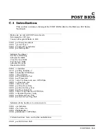
01AH post Dma InitJ, FAR
01CH post Reset PIC
;----------------------------------------------------------------------------
; Test the keyboard controller
; Compute the CPU clock speed
; Test the CMOS RAM
;----------------------------------------------------------------------------
022H
post I8742 Test, FAR
032H
post Compute Speed, FAR
034H
post Cmos Test, FAR
;----------------------------------------------------------------------------
; Optimize chipset timing
; Optimize other hardware
;----------------------------------------------------------------------------
03CH cs Adv Config
03DH post Adv Reg Config, OPTIONAL
;----------------------------------------------------------------------------
; Initialize interrupt vectors
; Make sure ROM copyright notice is intact
; Check for configuration errors
; Initialize the video
; Shadow the video
; Display the copyright notice
; Display the CPU type
; Initialize EISA bus
; Set segment limits back to 4GB (PCI code may have changed them)
;----------------------------------------------------------------------------
042H
post Vector Init, FAR
046H
post Copyright Check, FAR
047H
pci Op Rom Init
049H
pci Init
048H
post Config Check, FAR
04AH pci Video Init
04CH cs Video Shadow Config
024H
postSetHugeESJ
;----------------------------------------------------------------------------
; Test and initialize the keyboard
; Check for unexpected interrupts
; Display prompt "Press F2 to enter SETUP"
;----------------------------------------------------------------------------
052H
post KB Test, FAR
054H
feat Setup Keyclick, OPTIONAL, FAR
076H
post Keyboard Test, FAR
058H
post Hot Interrupt Test, FAR
;----------------------------------------------------------------------------
; Initialize QuietBoot if it's installed
; Note: Both the keyboard and timer interrupts (IRQ0 and IRQ1) are enabled
; here. Also, interrupts are enabled here and run through the end
; of POST. If your POST task requires interrupts to be off, please
; preserve them by doing a PUSHF, CLI at the beginning and a POPF at
; the end. If you change the PIC, please preserve existing bits.
; Display the copyright notice
; Display the CPU type
; Initialize EISA bus
Содержание Extensa 900 Series
Страница 1: ...Maintenance Manual ExtensaTM 900 Series Notebook Computers 9813715 0001 December 1996 ...
Страница 10: ......
Страница 28: ......
Страница 44: ......
Страница 56: ......
Страница 82: ......
Страница 98: ......
Страница 138: ...A 2 Notebook Schematic Diagrams Figure A 1 Notebook Main Board Logic Diagrams Sheet 1 of 30 ...
Страница 139: ...Notebook Schematic Diagrams A 3 Figure A 1 Notebook Main Board Logic Diagrams Sheet 2 of 30 ...
Страница 140: ...A 4 Notebook Schematic Diagrams Figure A 1 Notebook Main Board Logic Diagrams Sheet 3 of 30 ...
Страница 141: ...Notebook Schematic Diagrams A 5 Figure A 1 Notebook Main Board Logic Diagrams Sheet 4 of 30 ...
Страница 142: ...A 6 Notebook Schematic Diagrams Figure A 1 Notebook Main Board Logic Diagrams Sheet 5 of 30 ...
Страница 143: ...Notebook Schematic Diagrams A 7 Figure A 1 Notebook Main Board Logic Diagrams Sheet 6 of 30 ...
Страница 145: ...Notebook Schematic Diagrams A 9 Figure A 1 Notebook Main Board Logic Diagrams Sheet 8 of 30 ...
Страница 146: ...A 10 Notebook Schematic Diagrams Figure A 1 Notebook Main Board Logic Diagrams Sheet 9 of 30 ...
Страница 147: ...Notebook Schematic Diagrams A 11 Figure A 1 Notebook Main Board Logic Diagrams Sheet 10 of 30 ...
Страница 148: ...A 12 Notebook Schematic Diagrams Figure A 1 Motherboard PWB Logic Diagrams Sheet 11 of 23 ...
Страница 149: ...Notebook Schematic Diagrams A 13 Figure A 1 Notebook Main Board Logic Diagrams Sheet 12 of 30 ...
Страница 153: ...Notebook Schematic Diagrams A 17 Figure A 1 Notebook Main Board Logic Diagrams Sheet 16 of 30 ...
Страница 154: ...A 18 Notebook Schematic Diagrams Figure A 1 Notebook Main Board Logic Diagrams Sheet 17 of 30 ...
Страница 155: ...Notebook Schematic Diagrams A 19 Figure A 1 Notebook Main Board Logic Diagrams Sheet 18 of 30 ...
Страница 156: ...A 20 Notebook Schematic Diagrams Figure A 1 Notebook Main Board Logic Diagrams Sheet 19 of 30 ...
Страница 157: ...Notebook Schematic Diagrams A 21 Figure A 1 Notebook Main Board Logic Diagrams Sheet 20 of 30 ...
Страница 158: ...A 22 Notebook Schematic Diagrams Figure A 1 Notebook Main Board Logic Diagrams Sheet 21 of 30 ...
Страница 159: ...Notebook Schematic Diagrams A 23 Figure A 1 Notebook Main Board Logic Diagrams Sheet 22 of 30 ...
Страница 160: ...A 24 Notebook Schematic Diagrams Figure A 1 Notebook Main Board Logic Diagrams Sheet 23 of 30 ...
Страница 161: ...Notebook Schematic Diagrams A 25 Figure A 1 Notebook Main Board Logic Diagrams Sheet 24 of 30 ...
Страница 166: ...A 30 Notebook Schematic Diagrams Figure A 1 Notebook Main Board Logic Diagrams Sheet 29 of 30 ...
Страница 168: ......
Страница 171: ...MPB Schematic Diagrams B 3 Figure B 1 MPB CPU Board Logic Diagrams Sheet 2 of 3 ...
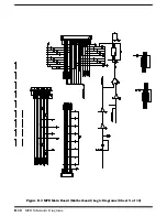
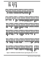
Страница 176: ...B 8 MPB Schematic Diagrams Figure B 3 MPB Main Board Motherboard Logic Diagrams Sheet 3 of 10 ...
Страница 178: ...B 10 MPB Schematic Diagrams Figure B 3 MPB Main Board Motherboard Logic Diagrams Sheet 5 of 10 ...
Страница 196: ......
Страница 197: ......
Страница 198: ......

