


5
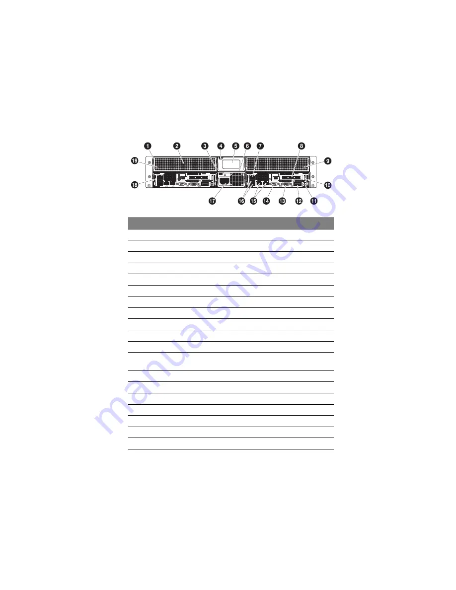
Rear panel
No.
Component
1
Server node module handle
2
Server node D
3
Server node release tab
4
Power supply module release latch
5
Dummy power supply module
6
Power supply module handle
7
Server management port (RJ-45) (10/100 Mbps)
8
PCI expansion slot
9
Server node B
10
Server node A
11
System ID switch
12
InfiniBand port QSFP connector (only available for AW170hd F1
and AW170hq F1)
13
Monitor port
14
Serial port (COM 1)
15
Gigabit LAN ports (10/100/1000 Mbps)
16
USB 2.0 ports
17
Power socket
18
Server node C
19
Server node D
Содержание AW170h F1
Страница 1: ...AW2000h Series User Guide AW170h F1 AW170hd F1 AW170hq F1 ...
Страница 16: ...xvi ...
Страница 17: ...1 System tour ...
Страница 25: ...9 The mainboard becomes accessible once you open the system It should look like the figure shown below ...
Страница 30: ...1 System tour 14 ...
Страница 31: ...2 System setup ...
Страница 38: ...2 System setup 22 ...
Страница 39: ...3 System upgrades ...
Страница 51: ...35 4 Insert the add on card 3 into the PCI slot 5 Secure the add on card with the locking tab 4 ...
Страница 70: ...3 System upgrades 54 ...
Страница 71: ...4 System BIOS ...
Страница 99: ...5 System troubleshooting ...
Страница 109: ...Appendix A Server management tools ...
Страница 114: ...Appendix A Server management tools 98 ...
Страница 115: ...Appendix B Rack mount configuration ...
Страница 126: ...Appendix B Rack mount configuration 110 ...
Страница 127: ...Appendix C Acer Smart Console ...
Страница 155: ...139 Exit Yes At the prompt click Yes to exit from remote redirection No Click No to return to the current session ...
Страница 156: ...Appendix C Acer Smart Console 140 ...
Страница 160: ...150 ...