41
White-Balance, Luminance Adjustment
Approximately 30 minutes should be allowed for warm up before proceeding white balance adjustment.
YPbPr Mode display adjustment
White balance adjustment (B)
General set-up :
Equipment Requirements: Minolta CA-110 or Equivalent Color analyzer
Quantum Data Pattern Generator 802G , 802BT or equivalent instrument
Input requirements:
Input Signal Type : YPbPr signal
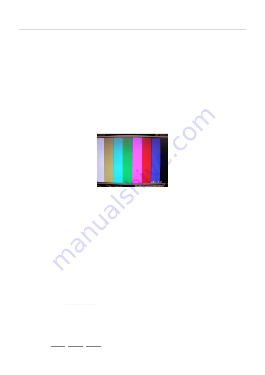
1. 720P mode, TVBar100 pattern by 802G or 802BT.
2. Select Smart picture to User mode and check the x, y data.
Input Signal Strength: 1 Vpp for Y signal ; 700 mVpp for Pb & Pr signal
Input Injection Point: YPbPr (RAC jack)
720P, TVBar100 pattern
Alignment method:
Initial Set-up:
1. Select source as “
Component
”.
2. Set Smart picture as “
User
” and to be Contrast =50
(TBD)
(CMO), Brightness=50
(TBD)
(CMO), at normal menu
mode.
3. Apply “TVBar100” pattern with color bar pattern by signal generator.
4. Enter factory mode menu: press “MENU+ “234” then enter FAC mode .
Alignment:
1. At FAC mode menu, select
FACTORY->Picture ->ADC -> Auto Colour
item. Then press “>” key to adjust
ADC_GAIN_R, ADC_GAIN_G, ADC_GAIN_B and ADC_OFFSET_R, ADC_OFFSET_G, ADC_OFFSET_B. Then
store those values to NVM.
White- Balance alignment :
1. Select source as “
HDMI1
”
2. Apply Flat pattern
(100% white pattern)
, at FAC mode menu, select
Factory -> Picture -> Colour Temp
item
3. Set color temperature to “
Standard
”.
4. Adjust the R Gain, G_Gain, B_Gain values to meet “Standard” color coordinates specification below. Then store
those values to NVM.
5. Set color temperature to “
Warm
”.
6. Adjust the R Gain, G_Gain, B_Gain values to meet “Warm” color coordinates specification below. Then store
those values to NVM.
7. Set color temperature to “
Cold
”.
8. Adjust the R Gain, G_Gain, B_Gain values to meet “Cold” color coordinates specification below. Then store
those values to NVM.
Chapter 7
Содержание AT3245
Страница 1: ...1 Acer AT3245 AT3246 Service Guide ...
Страница 7: ...7 Monitor Features General Specifications Chapter 1 ...
Страница 8: ...8 ...
Страница 11: ...11 Factory Preset Display Modes VGA HDMI Input Signal Reference Chart ...
Страница 13: ...13 Electrical Characteristics Optical Specifications Test Conditions Optical Specifications ...
Страница 14: ...14 Connecting Peripherals Front panel controls Chapter 2 ...
Страница 17: ...17 Using the OSD Menus ...
Страница 18: ...18 ...
Страница 19: ...19 ...
Страница 20: ...20 ...
Страница 21: ...21 ...
Страница 22: ...22 ...
Страница 23: ...23 ...
Страница 24: ...24 ...
Страница 27: ...27 3 Remove 4 screws to remove the bkt vesa top 4 Release the connectors ...
Страница 28: ...28 5 Remove the speakers 6 Remove the main board power board ...
Страница 29: ...29 7 Remove the bkt PCB holder 8 Release the key board and IR board 9 Remove the BKT panel support ...
Страница 30: ...30 10 Remove the bezel 11 Remove the 6 screws to release the panel ...
Страница 38: ...38 ...
Страница 39: ...39 II Set COM port resource that used by USB Port III Set Baud rate 115200 High speed item Enable MT537x MT ...
Страница 40: ...40 IV Click Upgrade button Waiting for Finished message V Main board Power Off _ On ...
Страница 44: ...44 Exploded Diagram Model AT3245 AT3246 ...
Страница 45: ...45 EDID Data DDC DATA for For D SUB Input EDID data 128 bytes ...
Страница 46: ...46 PCB Layout Main Board Layout Chapter 9 ...
Страница 47: ...47 ...
Страница 48: ...48 Power Board ...
Страница 49: ...49 Key Board IR board ...


