


116
Chapter 3
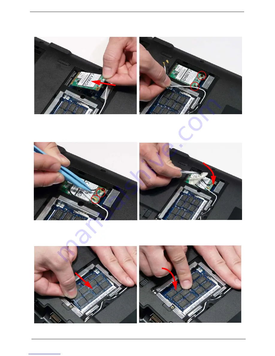
Replacing the WLAN Module
Replacing the DIMM Modules
1.
Insert the WLAN Module into the WLAN socket.
2.
Replace the two screws to secure the module.
3.
Connect the two Antenna cables to the module.
NOTE:
The black cable connects to the upper
terminal (MAIN) and the white cable to the
lower terminal (MAIN).
4.
After connecting the cables to the terminals,
secure the cables in place with adhesive tape to
avoid trapping.
1.
Insert the DIMM Module in place.
2.
Press down to lock the DIMM module in place.
3.
Repeat steps for the second DIMM module if present.
Содержание Aspire Z5751
Страница 6: ...VI ...
Страница 10: ...X Table of Contents ...
Страница 14: ...4 Chapter 1 System Block Diagram ...
Страница 34: ...24 Chapter 1 ...
Страница 72: ...62 Chapter 3 4 Disconnect the following four cables from the Mainboard A B C D ...
Страница 85: ...Chapter 3 75 4 Using both hands lift the Thermal Module clear of the Mainboard ...
Страница 87: ...Chapter 3 77 4 Lift the CPU Fan clear of the Mainboard as shown ...
Страница 93: ...Chapter 3 83 5 Lift the LCD Panel clear of the module ...
Страница 101: ...Chapter 3 91 9 The Antennas and cables appear as shown when correctly installed ...
Страница 106: ...96 Chapter 3 2 Replace the four screws and screw caps provided ...
Страница 111: ...Chapter 3 101 5 Replace the FFC and press down as indicated to secure it to the Upper Cover ...
Страница 115: ...Chapter 3 105 2 Press down around the edges to secure it in place 3 Replace the nine screws in the Upper Cover as shown ...
Страница 116: ...106 Chapter 3 4 Replace the three screw caps as shown 5 Connect the following cables to the Mainboard A B C D ...
Страница 122: ...112 Chapter 3 17 Replace the two screws securing the LCD Module to the Lower Cover ...
Страница 130: ...120 Chapter 3 ...
Страница 154: ...144 Chapter 5 ...
Страница 156: ...146 Chapter 6 Aspire 5517 Exploded Diagrams Main Assembly 1 2 3 4 5 ...
Страница 169: ...Chapter 6 159 ...
Страница 178: ...168 Appendix C ...
Страница 182: ...172 ...


