


Chapter 2
27
Setting a Password
Follow these steps as you set the user or the supervisor password:
1.
Use the
↑
and
↓
keys to highlight the Set Supervisor Password parameter and press the
Enter
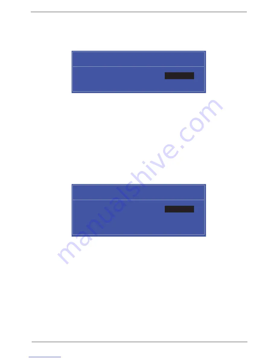
key. The
Set Supervisor Password box appears:
2.
Type a password in the “Enter New Password” field. The password length can not exceeds 8
alphanumeric characters (A-Z, a-z, 0-9, not case sensitive). Retype the password in the “Confirm New
Password” field.
IMPORTANT:
Be very careful when typing your password because the characters do not appear on the screen.
3.
Press
Enter
.
After setting the password, the computer sets the User Password parameter to “Set”.
4.
If desired, you can opt to enable the Password on boot parameter.
5.
When you are done, press F10 to save the changes and exit the BIOS Setup Utility.
Removing a Password
Follow these steps:
1.
Use the
↑
and
↓
keys to highlight the Set Supervisor Password parameter and press the
Enter
key. The
Set Password box appears:
2.
Type the current password in the Enter Current Password field and press
Enter
.
3.
Press
Enter
twice
without
typing anything in the Enter New Password and Confirm New Password fields.
The computer then sets the Supervisor Password parameter to “Clear”.
4.
When you have changed the settings, press
u
to save the changes and exit the BIOS Setup Utility.
S e t S u p e r v i s o r P a s s w o r d
E n t e r N e w P a s s w o r d [ ]
[ ]
C o n f i r m N e w P a s s w o r d [ ]
S e t S u p e r v i s o r P a s s w o r d
E n t e r C u r r e n t P a s s w o r d [ ]
[ ]
E n t e r N e w P a s s w o r d [ ]
C o n f i r m N e w P a s s w o r d [ ]
[ ]
Содержание Aspire Z5600 Series
Страница 6: ...VI ...
Страница 10: ...X Table of Contents ...
Страница 26: ...16 Chapter 1 ...
Страница 64: ...54 Chapter 3 5 Lift the Inverter Board clear of the device ...
Страница 81: ...Chapter 3 71 3 Secure the LCD Bracket using four 4 screws 4 Connect the left and right Control Board Cables ...
Страница 93: ...Chapter 3 83 4 Connect the cables on either side of the Inverter Board ...
Страница 99: ...Chapter 3 89 Replacing the SSD 1 Slide the SSD into the flange 2 Secure the SSD using one 1 screw as shown ...
Страница 101: ...Chapter 3 91 4 Secure the B CAS Board with three 3 screws ...
Страница 105: ...Chapter 3 95 4 Attach the EMI Cable Mylar to the Back Frame as shown ...
Страница 108: ...98 Chapter 3 3 Secure the Back Cover using fourteen 14 screws ...
Страница 128: ...118 Chapter 5 Bottom View Item Description RTC RTC battery socket ...
Страница 144: ...134 Chapter 6 ...
Страница 145: ...Chapter 6 135 ...
Страница 196: ...Appendix A 186 ...
Страница 208: ...198 Appendix C ...