


104
Chapter 4
ODD Failure
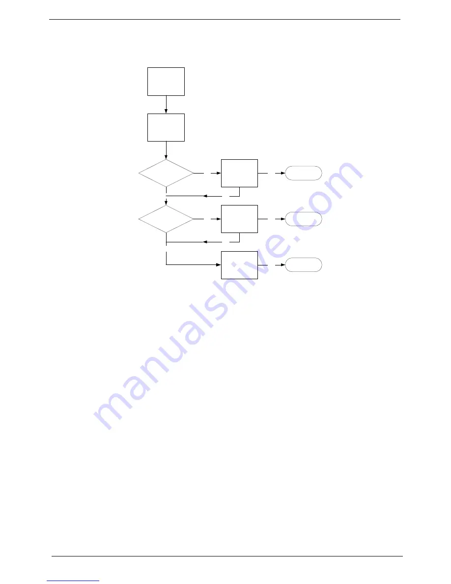
If an Optical Disk Drive failure is determined, use the following flowchart to determine the required action:
ODD Not Operating Correctly
If the
ODD
exhibits any of the following symptoms it may be faulty:
•
Audio CDs do not play when loaded
•
DVDs do not play when loaded
•
Blank discs do not burn correctly
•
DVD or CD play breaks up or jumps
•
Optical drive not found or not active:
•
Not shown in My Computer or the BIOS setup
•
LED does not flash when the computer starts up
•
The tray does not eject
•
Access failure screen displays
•
The ODD is noisy
Perform the following general solutions one at a time to correct the problem.
1.
Reboot the computer and retry the operation.
2.
Try an alternate disc.
3.
Navigate to
Start
´
Computer
. Check that the ODD device is displayed in the
Devices
with
Removable
Storage
panel.
4.
Navigate to
Start
´
Control
Panel
´
System
and
Maintenance
´
System
´
Device
Manager
.
a.
Double-click
lDE ATA/ATAPI controllers
. If a device displays a down arrow, right-click on the device
and click
Enable
.
START
Check DVD
cable connection
DVD does not
play
Reconnect
cable correctly
Check DVD
module
Replace ODD
module
Close
Close
Close
OK
NG
OK
OK
NG
NG
Replace
Mainboard
OK
NG
OK
Содержание Aspire Z5600 Series
Страница 6: ...VI ...
Страница 10: ...X Table of Contents ...
Страница 26: ...16 Chapter 1 ...
Страница 64: ...54 Chapter 3 5 Lift the Inverter Board clear of the device ...
Страница 81: ...Chapter 3 71 3 Secure the LCD Bracket using four 4 screws 4 Connect the left and right Control Board Cables ...
Страница 93: ...Chapter 3 83 4 Connect the cables on either side of the Inverter Board ...
Страница 99: ...Chapter 3 89 Replacing the SSD 1 Slide the SSD into the flange 2 Secure the SSD using one 1 screw as shown ...
Страница 101: ...Chapter 3 91 4 Secure the B CAS Board with three 3 screws ...
Страница 105: ...Chapter 3 95 4 Attach the EMI Cable Mylar to the Back Frame as shown ...
Страница 108: ...98 Chapter 3 3 Secure the Back Cover using fourteen 14 screws ...
Страница 128: ...118 Chapter 5 Bottom View Item Description RTC RTC battery socket ...
Страница 144: ...134 Chapter 6 ...
Страница 145: ...Chapter 6 135 ...
Страница 196: ...Appendix A 186 ...
Страница 208: ...198 Appendix C ...