


Chapter 5
107
Clearing Password Check and BIOS Recovery
This section provides the standard operating procedures for clearing the password and BIOS recovery for
Aspire 7740/7740G Series. There is one Hardware Open Gap on the main board for clearing the password
check and one Hotkey for enabling BIOS Recovery.
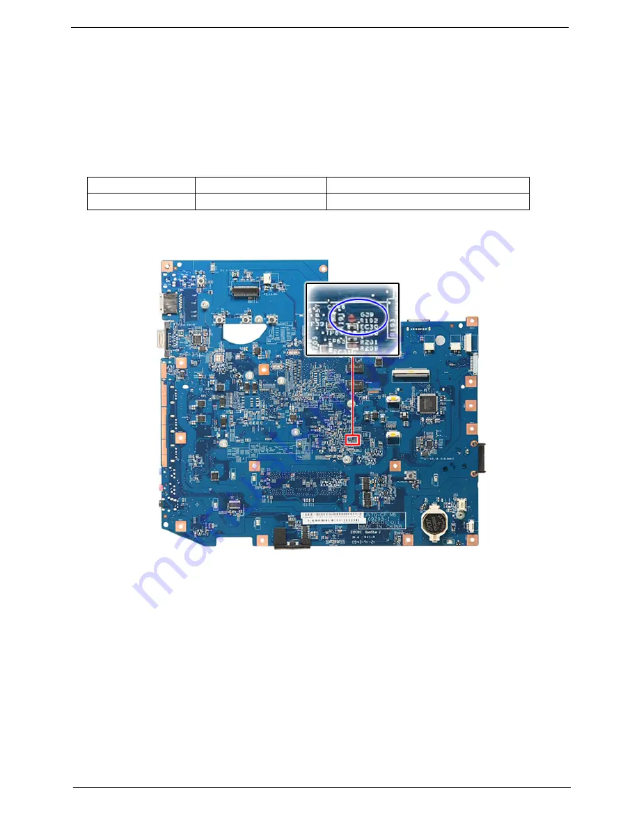
Clearing Password Check
Hardware Open Gap Description
HW Gap position on the main board:
Gap name in Aspire 7740/7740G Series is
G29
.
Steps for Clearing BIOS Password Check
If the user sets the BIOS Password (Supervisor Password and/or User Password) for a security reason, the
BIOS will ask for the password during system POST or when the system enters into the BIOS Setup menu. If
it is necessary to bypass the password check, the user needs to short the hardware gap to clear the password
by following these steps:
•
Power off the system, and remove the HDD, AC adapter and battery from the computer.
•
Open the back cover of the computer and look for the hardware gap on the main board as shown
in the picture(s) above.
•
Use an electric conductivity tool to short the two points of the hardware gap.
•
Plug in the AC adapter while retaining the short condition on the hardware gap. Press the power
button to turn on the computer until the BIOS POST routine is finished. Finally, remove the tool
from the hardware gap.
•
Restart the system. Press the F2 key to enter BIOS Setup menu.
Hardware
Default Setting
Operation Description
Gap
Open (Normal)
Short (Clearing Password Check)
Содержание Aspire 7740 Series
Страница 6: ...VI ...
Страница 12: ...4 Chapter 1 System Block Diagram ...
Страница 30: ...22 Chapter 1 ...
Страница 42: ...34 Chapter 2 ...
Страница 53: ...Chapter 3 47 4 Remove the DIMM module s ...
Страница 58: ...52 Chapter 3 NOTE When installing the CPU make sure to install the CPU with Pin 1 at the corner as shown ...
Страница 60: ...54 Chapter 3 3 Release the keyboard from the latches and turn it over on the palmrest area ...
Страница 75: ...Chapter 3 69 15 Remove the USB board module from the lower case ...
Страница 89: ...Chapter 3 83 10 Remove the LCD panel with brackets from the back cover ...
Страница 118: ...112 Chapter 5 ...
Страница 120: ...114 Chapter 6 Exploded Diagram ...
Страница 130: ...124 Chapter 6 ...
Страница 131: ...Appendix A 125 Model Definition and Configuration Appendix A ...
Страница 156: ...150 Appendix B ...
Страница 158: ...152 Appendix C ...